


23
Heat Controller, Inc. HEV/H SERIES Installation, Operation & Maintenance
ELECTRICAL - POWER WIRING
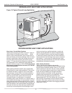
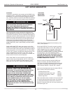
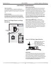
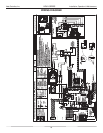
Figure 18: HR Single Phase Line Voltage
Field Wiring
Transformer
CXM
Control
Contactor -CC
BR
Low
Voltage
Connector
CB
L2
L1
Unit Power Supply
See electrical table for
breaker size
Grnd
Capacitor
Power Connection
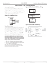
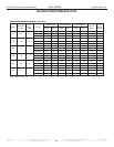
Line voltage connection is made by connecting the
incoming line voltage wires to the “L” side of the contactor
as shown in Figures 18. Consult Table 4 for correct fuse
size.
208 Volt Operation
All residential 208-230 Volt units are factory wired for
230 Volt operation. The transformer may be switched
to the 208V tap as illustrated on the wiring diagram by
switching the red (208V) and the orange (230V) wires at
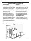
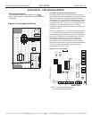
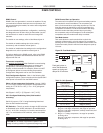
Blower Speed Selection
PSC (Permanent Split Capacitor) blower fan speed can
be changed by moving the blue wire on the fan motor
terminal block to the desired speed as shown in Figure
19. Units are shipped on the medium speed tap. Consult
engineering design guide for specific unit airflow tables.
Typical unit design delivers rated airflow at nominal
static (0.15 in. w.g. [37Pa]) on medium speed and rated
airflow at a higher static (0.4 to 0.5 in. w.g. [100 to 125
Pa]) on high speed for applications where higher static
is required. Low speed will deliver approximately 85% of
rated airflow at 0.10 in. w.g. [25 Pa].
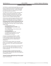
Special Note for ARI Testing: To achieve rated
airflow for ARI testing purposes on all PSC products,
it is necessary to change the fan speed to “HI” speed.
When the heat pump has experienced less than 100
operational hours and the coil has not had sufficient time
to be “seasoned”, it is necessary to clean the coil with a
mild surfactant such as Calgon to remove the oils left by
manufacturing processes and enable the condensate to
properly “sheet” off of the coil.
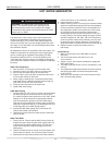
Connect the blue wire to:
H for High speed fan
M for Medium speed fan
L for Low speed fan
Medium is factory setting
Fan Motor
Figure 19: PSC Motor Speed Selection
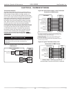
HWG Wiring
The hot water generator pump power wiring is disabled
at the factory to prevent operating the HWG pump “dry.”
After all HWG piping is completed and air purged from
the water piping, the pump power wires should be applied
to terminals on the HWG power block PB2 as shown in
the unit wiring diagram. This connection can also serve
as a HWG disable when servicing the unit.
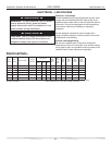
Figure 18: HE Single Phase Line Voltage
Field Wiring
AHRI
AHRI