


35
Heat Controller, Inc. HEV/H SERIES Installation, Operation & Maintenance
WARNING! When the disconnect switch is
closed, high voltage is present in some areas
of the electrical panel. Exercise caution when
working with energized equipment.
UNIT START-UP PROCEDURE
CAUTION! Verify that ALL water control
valves are open and allow water flow prior
to engaging the compressor. Freezing of the
coax or water lines can permanently damage
the heat pump.
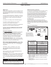
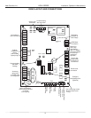
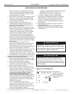
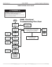
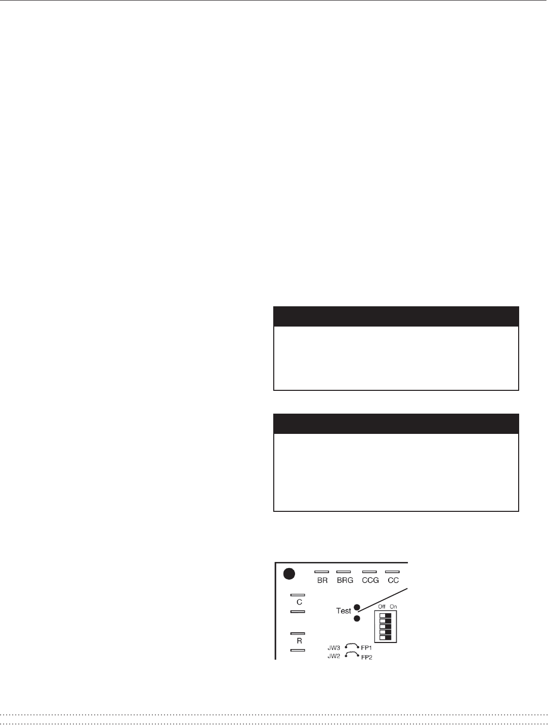
Short test pins
together to enter Test
Mode and speed-up
timing and delays for
20 minutes.
Figure 30: Test Mode Pins
Note: Units have a five minute time delay in the
control circuit that can be eliminated on the CXM
control board as shown below in Figure 30. See
controls description for details.
c. Verify that the compressor is on and that the water
flow rate is correct by measuring pressure drop
through the heat exchanger using the P/T plugs
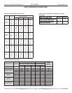
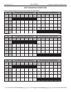
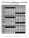
and comparing to Table 8.
d. Check the elevation and cleanliness of the
condensate lines. Dripping may be a sign of a
blocked line. Check that the condensate trap is
filled to provide a water seal.
e. Refer to Table 9. Check the temperature of both
entering and leaving water. If temperature is within
range, proceed with the test. If temperature is
outside of the operating range, check refrigerant
pressures and compare to Tables 10 through
12. Verify correct water flow by comparing unit
pressure drop across the heat exchanger versus
the data in Table 8. Heat of rejection (HR) can be
calculated and compared to catalog data capacity
pages. The formula for HR for systems with water
is as follows:
HR = TD x GPM x 500, where TD is the
temperature difference between the entering and
leaving water, and GPM is the flow rate in U.S.
GPM, determined by comparing the pressure drop
across the heat exchanger to Table 8.
f.
Check air temperature drop across the air coil when
compressor is operating. Air temperature drop
should be between 15°F and 25°F [8°C and 14°C].
g. Turn thermostat to “OFF” position. A hissing noise
indicates proper functioning of the reversing valve.
6. Allow five (5) minutes between tests for pressure to
equalize before beginning heating test.
a. Adjust the thermostat to the lowest setting. Place
the thermostat mode switch in the “HEAT” position.
b. Slowly raise the thermostat to a higher
temperature until the compressor activates.
c. Check for warm air delivery within a few minutes
after the unit has begun to operate.
d. Refer to Table 9. Check the temperature of both
entering and leaving water. If temperature is within
range, proceed with the test. If temperature is
outside of the operating range, check refrigerant
pressures and compare to Tables 10 through
12. Verify correct water flow by comparing unit
pressure drop across the heat exchanger versus
the data in Table 8. Heat of extraction (HE) can
be calculated and compared to submittal data
capacity pages. The formula for HE for systems
with water is as follows:
HE = TD x GPM x 500, where TD is the
temperature difference between the entering and
leaving water, and GPM is the flow rate in U.S.
GPM, determined by comparing the pressure drop
across the heat exchanger to Table 8.
e.
Check air temperature rise across the air coil when
compressor is operating. Air temperature rise should
be between 20°F and 30°F [11°C and 17°C].
f. Check for vibration, noise, and water leaks.
7. If unit fails to operate, perform troubleshooting
analysis (see troubleshooting section). If the check
described fails to reveal the problem and the unit
still does not operate, contact a trained service
technician to insure proper diagnosis and repair of
the equipment.
8. When testing is complete, set system to maintain
desired comfort level.
9. BE CERTAIN TO FILL OUT AND FORWARD ALL
WARRANTY REGISTRATION PAPERS TO HEAT
CONTROLLER.
Note: If performance during any mode appears abnormal,
refer to the CXM section or troubleshooting section of
this manual. To obtain maximum performance, the air
coil should be cleaned before start-up. A 10% solution of
dishwasher detergent and water is recommended.
ѥ WARNING! ѥ
ѥ CAUTION! ѥ
10C.
10C.
10C. Heat of rejection (HR) can be
Table 13. Verify
Table 10C. Heat of extraction (HE) can
correct water fl ow by comparing unit
UNIT START-UP PROCEDURE