


26
Installation, Operation & Maintenance HEV/H SERIES Heat Controller, Inc.
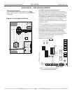
ELECTRICAL - THERMOSTAT WIRING
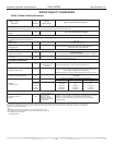
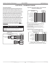
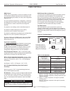
Figure 24: Typical Thermostat 2 Heat/1 Cool
Thermostat Installation
The thermostat should be located on an interior wall in a
larger room, away from supply duct drafts. DO NOT locate
the thermostat in areas subject to sunlight, drafts or on
external walls. The wire access hole behind the thermostat
may in certain cases need to be sealed to prevent erroneous
temperature measurement. Position the thermostat back
plate against the wall so that it appears level and so the
thermostat wires protrude through the middle of the back
plate. Mark the position of the back plate mounting holes
and drill holes with a 3/16” (5mm) bit. Install supplied
anchors and secure plate to the wall. Thermostat wire must
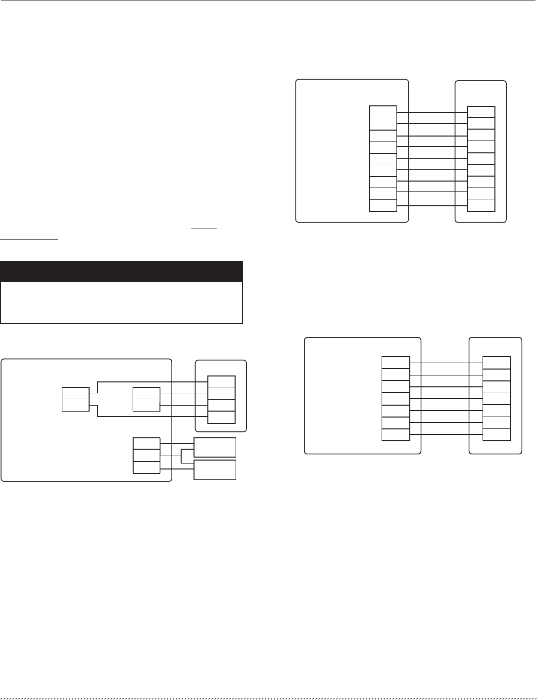
be 18 AWG wire. Wire the appropriate thermostat as shown
in Figures 24a and 24b to the low voltage terminal strip
on the DXM2 control board. Practically any heat pump
thermostat will work with these units, provided it has the
correct number of heating and cooling stages. However,
using the communicating thermostat (ATC32) is highly
recommended for on-site, easier confi guration, monitoring
and diagnosis.
ATM21U01 Thermostat
Connection to DXM2 Control
Compressor
Heating Stage 2
Reversing Valve
Fan
24Vac Hot
24Vac Common
Fault LED
Y
Y2/W
O
G
R
C
L
Y1
W
O
G
R
C
AL1
DXM2
(Using 2 Heat / 1 Cool thermostat is not
recommended if maximum efficiency is desired)
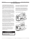
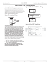
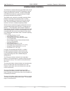
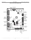
iGate™ Thermostat
ATC32U**
24Vac Hot
DXM2
24V
Comm +
A+
A+
Comm -
B-
B-
OD
ID
GND
Outdoor
Sensor
(Optiona)
Remote Indoor
Sensor
(Optiona)
24Vac Common
Gnd
R
C
Figure 23a: Communicating Thermostat Connection to
DXM2 Control
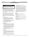
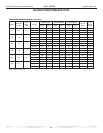
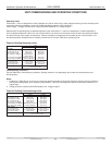
Figure 23b: Conventional 3 Heat / 2 Cool Thermostat
Connection to DXM2 Control
CAUTION!
CAUTION! Refrigerant pressure activated water regulating
valves should never be used with manufacturer’s
equipment.
Thermostat
Compressor
Compressor Stage 2
Reversing Valve
Fan
24Vac Hot
24Vac Common
Fault LED
DXM2
Board
Y1
Y2
W
H
O
G
R
C
AL1
Y1
Y2
W
DH
O
G
R
C
L
Dehumidification
Notes:
Auxiliary Heat
1) ECM automatic dehumidification mode operates with dehumidification airflows
in the cooling mode when the dehumidification output from thermostat is active.
Normal heating and cooling airflows are not affected.
2) DXM2 board DIP switch S2-7 must be in the auto dehumidification mode for
automatic dehumidification
3) DH connection not possible with units with internal pump. Use ATC32U**.
4) Only use ATC Communicating Thermostat when using Humidifier (H Input) with
units with internal flow controller.