


34
Installation, Operation & Maintenance HEV/H SERIES Heat Controller, Inc.
UNIT START-UP AND OPERATING CONDITIONS
Unit and System Checkout
BEFORE POWERING SYSTEM, please check the following:
UNIT CHECKOUT
Shutoff valves: Insure that all isolation valves are open.
Line voltage and wiring: Verify that voltage is within
an acceptable range for the unit and wiring and fuses/
breakers are properly sized. Verify that low voltage wiring
is complete.
Unit control transformer: Insure that transformer has the
properly selected voltage tap. Residential 208-230V units
are factory wired for 230V operation unless specifi ed
otherwise.
Loop/water piping is complete and purged of air. Water/
piping is clean.
Antifreeze has been added if necessary.
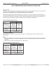
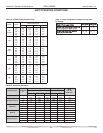
Entering water and air: Insure that entering water and air
temperatures are within operating limits of Tables 9a and
9b.
Low water temperature cutout: Verify that low water
temperature cut-out on the DXM2 control is properly set.
Unit fan: Manually rotate fan to verify free rotation and
insure that blower wheel is secured to the motor shaft.
Be sure to remove any shipping supports if needed.
DO NOT oil motors upon start-up. Fan motors are pre-
oiled at the factory. Check unit fan speed selection and
compare to design requirements.
Condensate line: Verify that condensate trap is installed
and pitched.
HWG pump is disconnected unless piping is completed
and air has been purged from the system.
Water fl ow balancing: Record inlet and outlet water
temperatures for each heat pump upon startup. This
check can eliminate nuisance trip outs and high velocity
water fl ow that could erode heat exchangers.
Unit air coil and fi lters: Insure that fi lter is clean and
accessible. Clean air coil of all manufacturing oils.
Unit controls: Verify that DXM2 fi eld selection options are
properly set. Low voltage wiring is complete.
Blower CFM and Water ∆T is set on communicating
thermostats or diagnostic tool.
Service/access panels are in place.
SYSTEM CHECKOUT
System water temperature: Check water temperature
for proper range and also verify heating and cooling set
points for proper operation.
System pH: Check and adjust water pH if necessary to
maintain a level between 6 and 8.5. Proper pH promotes
longevity of hoses and fi ttings (see Table 3).
System fl ushing: Verify that all air is purged from the
system. Air in the system can cause poor operation or
system corrosion. Water used in the system must be
potable quality initially and clean of dirt, piping slag,
and strong chemical cleaning agents. Some antifreeze
solutions may require distilled water.
Internal Flow Controller: Verify that it is purged of air and
in operating condition.
System controls: Verify that system controls function and
operate in the proper sequence.
Low water temperature cutout: Verify that low water
temperature cut-out controls are set properly
(LT1 - JW3).
Miscellaneous: Note any questionable aspects of
the installation.
Unit Start-up Procedure
1. Turn the thermostat fan position to “ON.” Blower
should start.
2. Balance air fl ow at registers.
3. Adjust all valves to their full open position. Turn on the
line power to all heat pump units.
4. Room temperature should be within the minimum-
maximum ranges of Table 9b. During start-up checks,
loop water temperature entering the heat pump should
be between 30°F [-1°C] and 95°F [35°C].
5. It is recommended that water-to-air units be fi rst started
in the cooling mode, when possible. This will allow liquid
refrigerant to fl ow through the fi
lter-drier before entering
the TXV, allowing the fi lter-drier to catch any debris that
might be in the system before it reaches the TXV.
6.
Two factors determine the operating limits of geothermal
heat pumps, (a) return air temperature, and (b) water
temperature. When any one of these factors is at a
minimum or maximum level, the other factor must be at
normal level to insure proper unit operation.
a. Adjust the unit thermostat to the warmest setting.
Place the thermostat mode switch in the “COOL”
position. Slowly reduce thermostat setting until the
compressor activates.
b. Check for cool air delivery at the unit grille within a
few minutes after the unit has begun to operate.
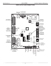
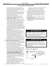
Note: Units have a fi ve minute time delay in the
control circuit that can be bypassed on the DXM2
control board as shown below in Figure 25. See
controls description for details.
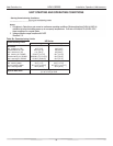
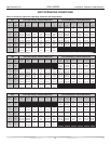
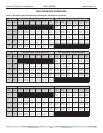
c. Verify that the compressor is on and that the water
fl ow rate is correct by measuring pressure drop
through the heat exchanger using the pressure ports
and comparing to Table 10.
d. Check the elevation and cleanliness of the
condensate lines. Dripping may be a sign of a
blocked line. Check that the condensate trap is fi lled
CAUTION!
CAUTION!
CAUTION! To avoid equipment damage, DO NOT
leave system fi lled in a building without heat during the
winter unless antifreeze is added to the water loop. Heat
exchangers never fully drain by themselves and will
freeze unless winterized with antifreeze.
CAUTION! Verify that ALL water valves are open and
allow water fl ow prior to engaging the compressor.
Freezing of the coax or water lines can permanently
damage the heat pump.