


44
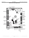
Installation, Operation & Maintenance HEV/H SERIES Heat Controller, Inc.
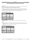
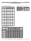
TROUBLESHOOTING FORM
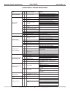
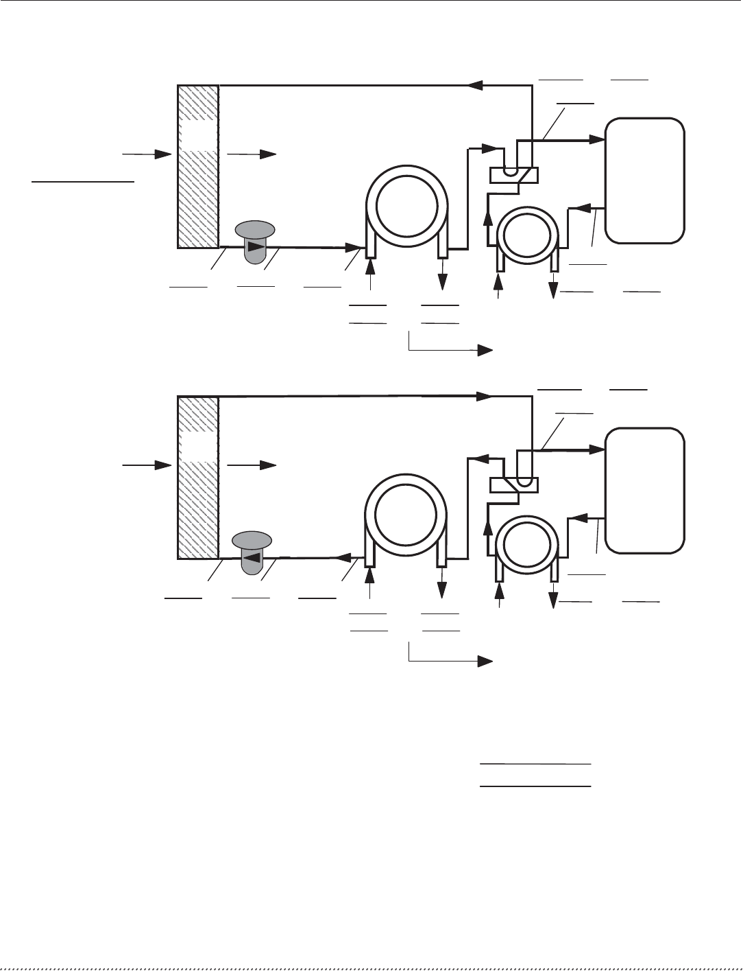
COAX
COMPRESSOR
DISCHARGE
SUCTION
HWG
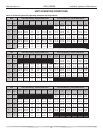
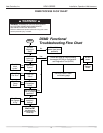
COOLING CYCLE ANALYSIS -
COAX
COMPRESSOR
DISCHARGE
SUCTION
HWG
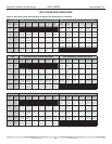
HEATING CYCLE ANALYSIS -
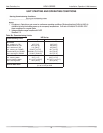
PSI
SAT
PSI
SAT
°F
°F
AIR
COIL
°F °F
FP2: HEATING
LIQUID LINE
°F
EXPANSION
VALVE
AIR
COIL
°F °F
PSI
SAT
PSI
SAT
°F
°F
°F °F
WATER IN WATER OUT
PSI PSI
°F °F
WATER IN WATER OUT
PSI PSI
Heat of Extraction (Absorption) or Heat of Rejection =
________ flow rate ( diff. ( factor = _____________
(Btu/hr)
Superheat
Subcooling
Suction temperature - suction saturation temp.
Discharge saturation temp. -liquid line temp.
=
=
=
=
(deg F)
(deg F)
Look up pressure drop in
I.O.M. or spec. catalog to
determine flow rate.
Look up pressure drop in
I.O.M. or spec. catalog to
determine flow rate.
†
Use 500 for water, 485 for antifreeze.
FLASH
GAS LINE
°F
FP1
SENSOR
°F
EXPANSION
VALVE
FP2: FLASH
GAS LINE
°F
OTHER SIDE
OF FILTR DR
°F
FP1: CLG
LIQ LINE
°F
Refrigerant Type :
R22
gpm) x ________ temp. deg. F) x ________ fluid
†
Note: Never connect refrigerant gauges during startup procedures. Conduct water-side analysis
using P/T ports to determine water flow and temperature difference. If water-side analysis shows
poor performance, refrigerant troubleshooting may be required. Connect refrigerant gauges as a
last resort.
R-410A