


24
Installation, Operation & Maintenance HEV/H SERIES Heat Controller, Inc.
ELECTRICAL - L
O
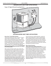
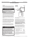
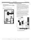
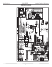
Figure 21: Low Voltage Field Wiring
Thermostat Connections
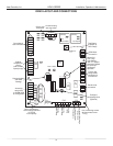
The thermostat should be wired directly to the CXM
board. See “Electrical – Thermostat” for specific terminal
connections.
Rev.: 3/24/00
BR
Contactor - CC
Capacitator
Loop PB1 HWG PB2
CXM Control
Low Voltage
Connector
Transformer
CB
Circ Brkr
Grnd
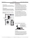
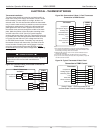
ELECTRICAL - LOW VOLTAGE WIRING
DXM 2
Comp
Relay
24Vdc
EH1
EH2
P6
Off On
JW3
c
1
a
y
c
2
a
y
CO
RV
RV
LT1
LT1
LT2
LT2
LP
LP
HP
P7
Status
Fault
CC
CCG
CO
S1
S2
12
1
4
Off On
AO2
P11
Gnd
T1
P10
T2 T2 T3 T3 T4 T4
T5
P9
T5
T6 T6
A0-1 A0-2
Off On
S3
RV
Relay
CCH
Relay
1 2 3 4
1 2 3 4 5 6 7 8
1 2 3 4 5 6 7 8
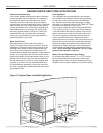
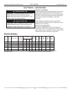
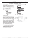
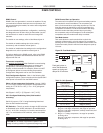
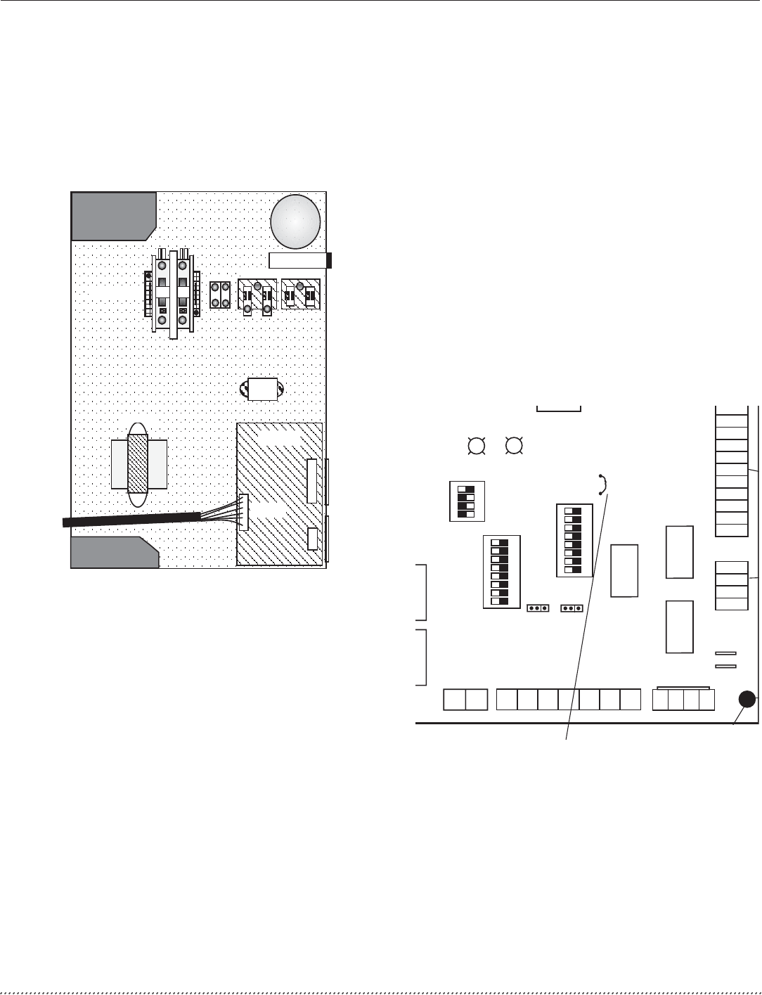
Figure 22: LT1 Limit Setting
DXM2 PCB
JW3-LT1 jumper should be clipped
for low temperature operation
Low Water Temperature Cutout Selection
The DXM2 control allows the fi eld selection of low water (or
water-antifreeze solution) temperature limit by clipping jumper
JW3, which changes the sensing temperature associated
with thermistor LT1. Note that the LT1 thermistor is located on
the refrigerant line between the coaxial heat exchanger and
expansion device (TXV). Therefore, LT1 is sensing refrigerant
temperature, not water temperature, which is a better
indication of how water fl ow rate/temperature is affecting the
refrigeration circuit.
The factory setting for LT1 is for systems using water (30°F
[-1.1°C] refrigerant temperature). In low water temperature
(extended range) applications with antifreeze (most ground
loops), jumper JW3 should be clipped as shown in Figure
19 to change the setting to 10°F [-12.2°C] refrigerant
temperature, a more suitable temperature when using
an antifreeze solution. All residential units include water/
refrigerant circuit insulation to prevent internal condensation,
which is required when operating with entering water
temperatures below 59°F [15°C].
DXM2