


Heat & Glo • PIER/ST/L&RCOR-HVB-CE • 2068-900 Rev. H • 6/0720
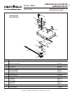
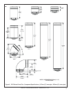
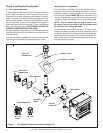
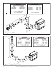
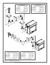
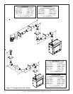
Figure 7. Flue System Components and Termination Kits
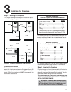
Step 3. Installing the Flue System
A. Flue System Approvals
These models are approved to use DVP series direct flue
pipe components and terminations (see Figures 6 and 7).
Approved flue system components are labeled for identifi-
cation. This pipe is tested and listed as an approved com-
ponent of the fireplace. The pipe is tested to be run inside
an enclosed wall. There is no requirement for inspection
openings at each joint within the wall. There is no required
pitch for horizontal flue runs. NO OTHER FLUEING SYS-
TEMS OR COMPONENTS MAY BE USED.
Detailed installation instructions are included with each flue
termination kit and should be used in conjunction with this
Installers Guide.
The flame and ember appearance may vary based on the
type of fuel burned and the flueing configuration used.
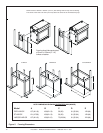
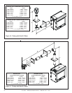
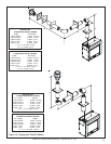
Identifying Flue Components
The flue systems installed on this gas fireplace may in-
clude one, two, or three 90°
elbow assemblies. The rela-
tionships of vertical rise to horizontal run in flue configura-
tions using 90° elbows MUST BE strictly adhered to. The
rise to run relationships are shown in the flueing drawings
and tables. Refer to the diagrams on the next several pages.
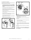
NOTE: Two 45° elbows may be used in place of one
90° elbow. Rise to run ratios in the flue system must
be followed if 45° elbows are used.
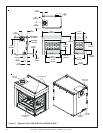
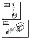
This model has a 45
0
elbow built into it. It may be posi-
tioned to flue either horizontal or vertical. Depending on the
installation, decide which direction the elbow should be fac-
ing. Remove the 8 screws from the corner cover plate. Po-
sition the 45
0
elbow as desired and replace the corner cov-
er plate with the 8 screws.
HORIZONTAL
TERMINATION
WALL FIRESTOP
90 DEGREE
ELBOW
PIPE LENGTH
CEILING
FIRESTOP
VERTICAL
TERMINATION
STORM COLLAR
ROOF FLASHING
Terminations Kits
DVP-TVHW
DVP-TRAP
SERIES