


Heat & Glo • PIER/ST/L&RCOR-HVB-CE • 2068-900 Rev. H • 6/07
17
3
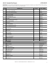
Installing the Fireplace
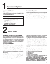
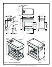
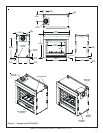
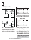
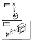
Step 1. Locating the Fireplace
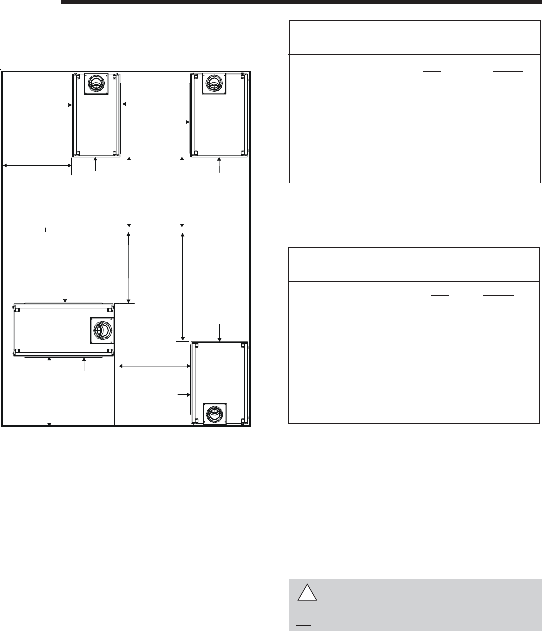
The diagram below shows space and clearance require-
ments for locating a fireplace within a room.
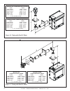
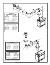
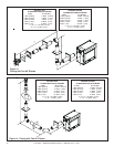
Minimum Clearances
from the Fireplace to Combustible Materials
Figure 4. Fireplace Dimensions and Locations
Clearance Requirements
The top, back, and sides of the fireplace are defined by
stand-offs. The minimum clearance to a perpendicular wall
extending past the face of the fireplace is 25 mm (1 in.). The
metal ends of the fireplace may NOT be recessed into
combustible construction.
For minimum clearances, see the direct flue termination
clearance diagrams on pages 30 and 31 in this manual.
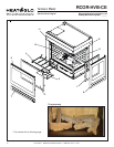
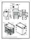
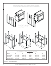
Step 2. Framing the Fireplace
Fireplace framing can be built before or after the fireplace is
set in place. Framing should be positioned to accommo-
date wall coverings and fireplace facing material. The dia-
gram below shows framing reference dimensions.
CAUTION: MEASURE FIREPLACE DIMENSIONS AND
VERIFY FRAMING METHODS AND WALL COVERING
DETAILS BEFORE FRAMING.
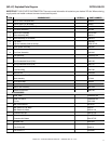
Minimum Clearances
from the Flue Pipe to Combustible Materials
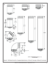
* The clearance to the ceiling is measured from the top of
the unit, excluding the standoffs (see Figures 37 & 38).
The distance from the unit to combustible construction is to
be measured from the unit outer wrap surface to the com-
bustible construction, NOT from the screw heads that se-
cure the unit together.
!
WARNING: FRAMING DIMENSIONS ASSUME
USE OF 1/2 INCH THICK WALL COVERING
MATERIALS ON EXTERIOR OF FRAMING ONLY AND
NO SHEETROCK ON INTERIOR OF FRAMING.
914 mm
GLASS
GLASS
GLASS
914 mm
GLASS
GLASS
914 mm
GLASS
914 mm
GLASS
GLASS
GLASS
914 mm
914 mm
914 mm
PIER-HVB-CE
TOP VIEW
RCOR-HVB-CE
TOP VIEW
LCOR-HVB-CE
TOP VIEW
ST-HVB-CE
TOP VIEW
mm inches
Glass Sides or Ends......... 914..................... 36
Floor ................................... 0 ....................... 0
Rear Flue ........................... 13 ..................... 1/2
Metal Sides or Ends .......... 13 ..................... 1/2
Top..................................... 64 ................... 2 1/2
Ceiling* ............................. 787..................... 31
mm Inches
Vertical Sections. ............ 25 ................ 1
Horizontal Sections
Top .................................... 75 ................ 3
Bottom .............................. 25 ................ 1
Sides ................................ 25 ................ 1
At Wall Firestops
Top ................................... 63.7 ............ 2 1/2
Bottom .............................. 13 ...............1/2
Sides ................................ 25 ................ 1