


02-02 7 26678 Rev H
GBI25 SERIES B-VENT GAS FIRED FIREPLACE INSERT
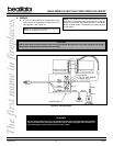
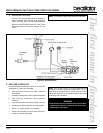
Seal with high temperature silicone at the point where
the gas line enters the existing fireplace to prevent
cold air infiltration.
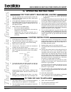
This fireplace has been altered to
accommodate an insert and should be
inspected by a qualified service technician
prior to re-use as a conventional fireplace.
Note: The above label, located in the instruction
package, must be affixed to the existing fireplace prior
to installation of the GBi25 Gas Fired Fireplace Insert.
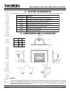
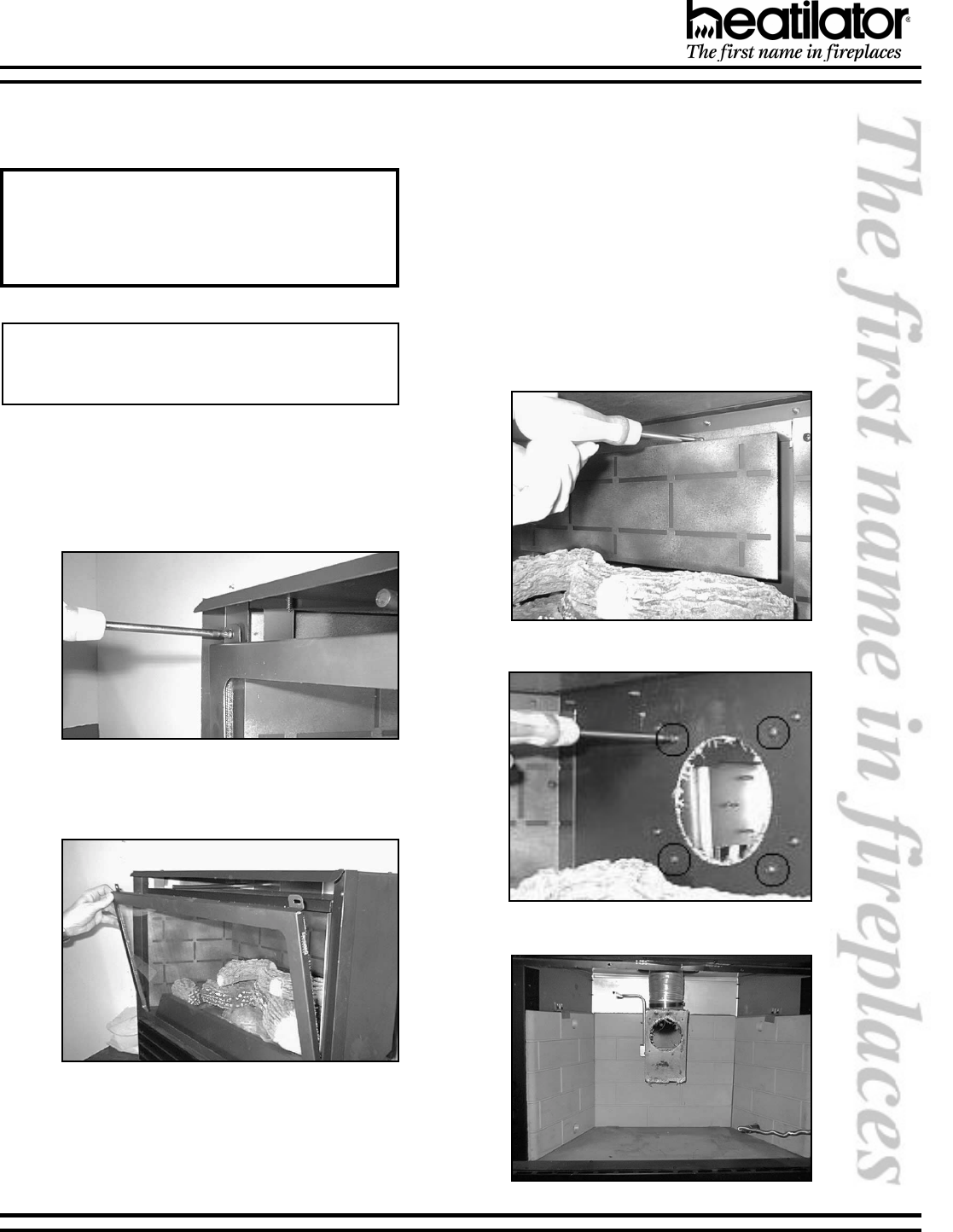
3. APPLIANCE INSTALLATION
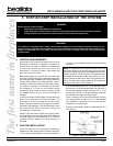
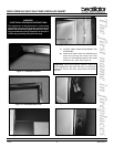
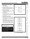
a. Firebox Entry
To gain access to the draft hood, remove the two
screws located in the upper corners of the glass
frame. See Figure 2.
Figure 2 - Firebox Entry
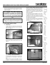
Figure 3 - Glass Frame Removal
Rotate glass frame forward and lift out. See
Figure3.
Handle the glass frame with care to avoid striking
or scratching it on hard objects or slamming it
shut.
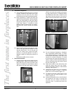
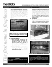
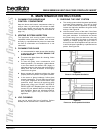
Remove the two screws on the baffle, as shown
in Figure 4. To remove the draft hood, unscrew
the four screws located around the exhaust
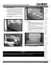
opening. See Figure 5. Slide the draft hood out of
the appliance and attach draft hood to flex liner in
appliance with a minimum of three sheet metal
screws. A 4 diameter hose clamp may also be
used. See Figure 6.
The draft hood must be installed so as to be in
the same atmospheric pressure zone as the
combustion air inlet to the appliance and shall
be located so that the relief opening is accessible
for checking vent operation.
Pack the area at the damper with noncombustible
insulation to prevent cold air infiltration into the
fireplace cavity.
Figure 4 - Baffle Removal
Figure 5 - Draft Hood Removal
Figure 6 - Draft Hood Attachment
Label