


26678 Rev H 10 02-02
GBI25 SERIES B-VENT GAS FIRED FIREPLACE INSERT
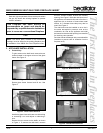
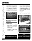
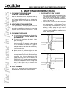
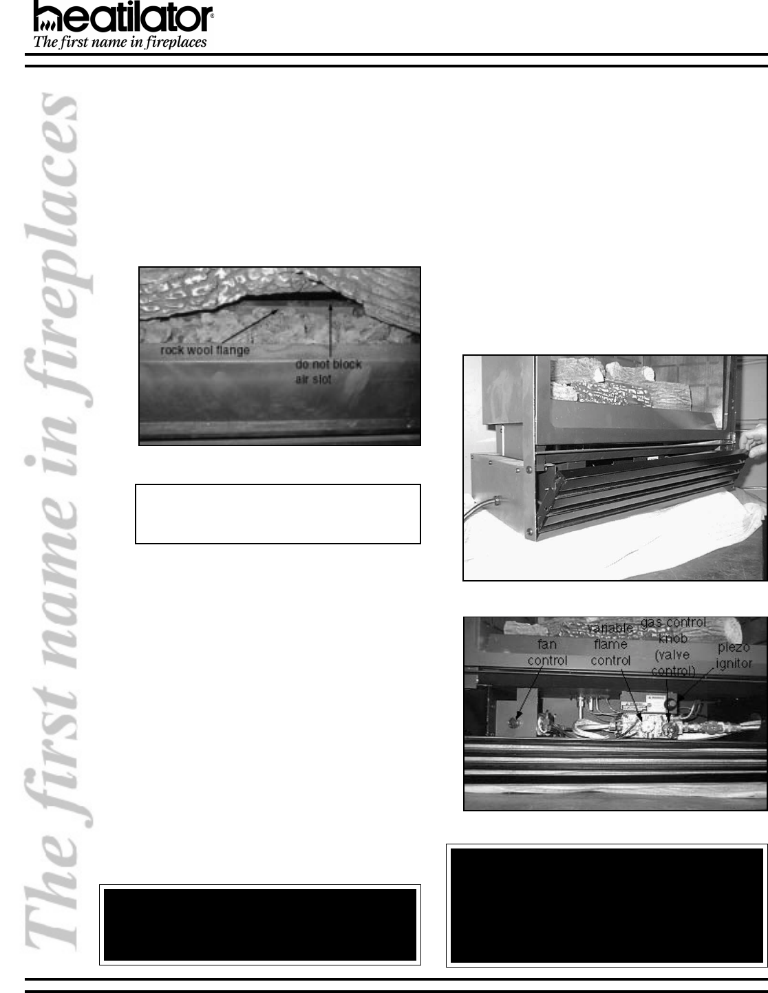
d. Rock Wool Placement
The log set is shipped in place. Tear the rock
wool into pieces no larger than 1/2 diameter.
Place the rock wool in front of the flange located
in the middle of the burner. Do not place the rock
wool behind or above the 3/8 flange. This will
block the air slot and cause carbon desposits on
the log. Place the rock wool on both the left and
right sides to complete the burning ember look. It
is not necessary to use the entire bag. See
Figure17.
Figure 17 - Rock Wool Placement
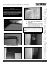
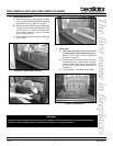
e. Glass Frame Installation
1) When cleaning the glass, use only non-
caustic, non-abrasive cleaners. DO NOT
ATTEMPT TO CLEAN HOT GLASS. It is
dangerous, and the glass is more likely to
be stained by the cleaning agent. Stubborn
film can often be removed using Brasso® or
a non-abrasive cleaner.
2) After cleaning the glass, position the tabs on
the glass frame into the slots on the column
of the appliance. Hold door in place and
secure with screws removed earlier. Be
careful not to over-tighten.
Note: Placement of the rock wool should be done
with care and time, as this will create the look of
the fire when burning.
WARNING!
Never operate this appliance with the glass removed
or not sealed.
WARNING!
Do not operate appliance with the panel(s) removed,
cracked or broken. Replacement of the panel(s)
should be done by a licensed or qualified service
person.
f. Brass Trim Cleaning
All prints and smudges must be wiped clean from
the brass trim prior to initial burn. If this is not
done, these prints will be cured into the brass
finish and set for the life of the appliance. To keep
the finish looking its best, gently wipe with a soft
cloth after the appliance has had ample time to
cool down. If desired, use a non-abrasive cleaner
such as soap and water. Never use any solvent,
thinner or abrasive cleaner since these will
damage the finish.
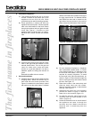
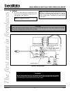
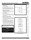
g. Valve Access
The valve is located behind the control access
panel. Lift the panel up and rotate forward. See
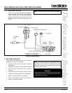
Figure18. This will expose the gas valve, variable
regulator and fan control, as shown in Figure 19.
Figure 18 - Valve Access
Figure 19 - Gas Valve, Variable Regulator & Fan Control