


Heat & Glo • 6000G, 6000G-IPI • 2103-900 Rev. O • 12/0860
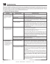
B. Intellifi re Ignition System
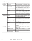
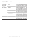
Symptom Possible Cause Corrective Action
1. Pilot won’t light.
The ignitor/module
makes noise, but no
spark.
A. Incorrect wiring. Verify “S” wire (white) for sensor and “I” wire (orange) for ignitor are
connected to correct terminals on module and pilot assembly.
B. Loose connections or electrical
shorts in the wiring.
Verify no loose connections or electrical shorts in wiring from mod-
ule to pilot assembly. Verify connections underneath pilot assem-
bly are tight; also verify connections are not grounding out to metal
chassis, pilot burner, pilot enclosure, mesh screen if present, or any
other metal object.
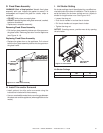
C. Ignitor gap is too large. Verify gap of igniter to right side of pilot hood. The gap should be
approximately .17 in. or 1/8 in. (3 mm).
D. Module. Turn ON/OFF rocker switch or wall switch to OFF position. Remove
ignitor wire “I” from module. Place a grounded wire about 3/16 in. (5
mm) away from “I” terminal on module. Place ON/OFF rocker switch
or wall switch in ON position. If there is no spark at “I” terminal module
must be replaced. If there is a spark at “I” terminal, module is fi ne.
Inspect pilot assembly for shorted sparker wire or cracked insulator
around electrode. Replace pilot if necessary.
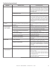
2. Pilot won’t light,
there is no noise or
spark.
A. No power or transformer installed
incorrectly.
Verify that transformer is installed and plugged into module. Check
voltage of transformer under load at spade connection on module
with ON/OFF switch in ON position. Acceptable readings of a good
transformer are between 3.2 and 2.8 volts AC.
B. A shorted or loose connection in
wiring confi guration or wiring har-
ness.
Remove and reinstall the wiring harness that plugs into module.
Verify there is a tight fi t. Verify pilot assembly wiring to module. Re-
move and verify continuity of each wire in wiring harness. Replace
any damaged components.
C. Improper wall switch wiring. Verify that 110/VAC power is “ON” to junction box.
D. Module not grounded. Verify black ground wire from module wire harness is grounded to
metal chassis of appliance.
E. Module. Turn ON/OFF rocker switch or wall switch to OFF position. Remove
ignitor wire “I” from module. Place ON/OFF rocker switch or wall
switch in ON position. If there is no spark at “I” terminal module
must be replaced. If there is a spark at “I” terminal, module is fi ne.
Inspect pilot assembly for shorted sparker wire or cracked insulator
around electrode.
3. Pilot sparks, but
Pilot will not light.
A. Gas supply. Verify that incoming gas line ball valve is “open”. Verify that inlet
pressure reading is within acceptable limits, inlet pressure must not
exceed 14 in. W.C.
B. Ignitor gap is too large. Verify gap of igniter to right side of pilot hood. The gap should be
approximately .17 in. or 1/8 in. (3 mm).
C. Module is not grounded. Verify module is securely grounded to metal chassis of appliance.
D. Module voltage output / Valve/Pilot
solenoid ohms readings.
Verify battery voltage is at least 2.7 volts. Replace batteries if volt-
age is below 2.7.