


Heat & Glo • 6000G, 6000G-IPI • 2103-900 Rev. O • 12/0850
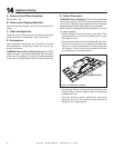
E. Electrical Service and Repair
WARNING! Risk of Shock! Label all wires prior to dis-
connection when servicing controls. Wiring errors can
cause improper and dangerous operation. Verify proper
operation after servicing.
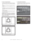
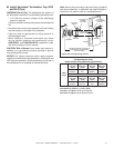
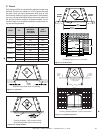
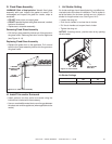
Figure 12.2 Intellifi re Pilot Ignition (IPI) Wiring Diagram
Figure 12.3 Standing Pilot Ignition Wiring Diagram
WARNING! Risk of Shock! Replace damaged wire with
type 105º C rated wire. Wire must have high temperature
insulation.
THERMOSTAT
WIRE ASSEMBLY
ON/OFF PIGGYBACK WIRE
BRN
VALVE
WHT
RED
RED
STANDING
PILOT
PLUG-IN
3V TRANSFORMER
ON/OFF
WALL SWITCH
IGNITION
MODULE
(3V)
VALVE
NEUTRAL
GROUND
LOWVOLTAGE
SEE NOTE 1
REMOTE
CONTROL HOT
PLUG-IN
REMOTE
JUMPERWIRE
ORG
GRN
BRN
BRN
RED
BLK
INTERMITTENT
PILOTIGNITOR
ORG
WHT
IGNITION MODULE 3 VAC
TRANSFORMER
VALVE
3 VAC
THERMOSTAT
WIRE
ASSEMBLY
BLACKWIRE CANBE
PLUGGEDINTOANY
OF #1 - #5 LOCATIONS
ON THE HOTSIDE
WHITEWIRE CAN BE
PLUGGEDINTO ANY
OF#1 - #5 LOCATIONS
ONTHE NEUTRAL SIDE
GROUNDTO
FIREPLACE
CHASSIS*