


Heat & Glo • 6000G, 6000G-IPI • 2103-900 Rev. O • 12/0828
H
1
V
1
V
2
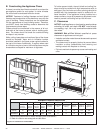
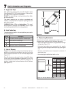
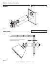
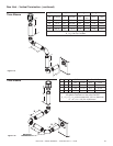
Top Vent - Vertical Termination (continued)
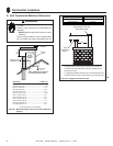
Figure 7.11
Two Elbows
Figure 7.10
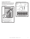
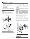
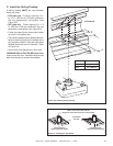
4. Center the Flue Restrictor on vent and secure in place
by using two self-tapping screws (see Figure 7.10).
5. Reinstall the Exhaust Shield.
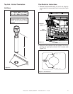
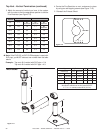
3. Match the amount of vertical you have in the system
with the chart to fi nd the appropriate position to set the
Flue Restrictor (see Figure 7.9).
Figure 7.9
1 2 3 4 5
SETTING
1 2 3 4 5
Vertical
TOP VENT REAR VENT
NG LP NG LP
4 ft. 1-1
No
Restrictor
No
Restrictor
No
Restrictor
8 ft. 2-2 1-2 1-1
No
Restrictor
15 ft. 3-3 3-2 2-2 1-2
20 ft. 3-4 3-3 3-3 2-3
25 ft. 3-4 3-3 3-3 2-3
30 ft. 4-4 3-4 3-4 3-3
35 ft. 4-4 3-4 3-4 3-3
40 ft. 5-4 4-4 4-4 3-4
V
1
H
1
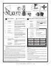
Maximum V
2
V
1
+ V
2
Min.
Elbow only 2 ft. 610 mm * * *
6 in. 152 mm 6 ft. 1.8 m * * *
2 ft. 610 mm 11 ft. 3.4 m * * *
3 ft. 914 mm 16 ft. 4.9 m * * *
4 ft. 1.2 m 20 ft 6.1 m * * *
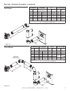
V
1
+ V
2
+ H
1
= 50 ft (15.2 m) Maximum
*No specifi c restrictions on this value EXCEPT
V
1
+ V
2
+ H
1
cannot exceed 50 ft (15.2 m)
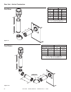
Note: If the DVP-2SL or DVP-SLP24 adapter is used with
SLP pipe, you MUST subtract one number from the table
above.
Example: Top vent 40 ft vertical with DVP pipe = 5-4
Top vent 40 ft vertical with SLP pipe = 4-3