


Heat & Glo • 6000G, 6000G-IPI • 2103-900 Rev. O • 12/0836
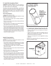
D. Install Attic Insulation Shield
WARNING! Fire Risk. DO NOT allow loose materials or
insulation to touch vent. Hearth & Home Technologies
Inc. requires the use of an attic shield.
The National Fuel Gas Code ANSI Z223.1 and NFPA 54
requires an attic shield constructed of 26 gauge minimum
metal that extends at least 2 in. (51 mm) above insulation.
Attic shields must meet specifi ed clearance and be se-
cured in place.
Flat Ceiling Installation
• Remove one shield from box.
NOTICE: Cut previously installed batt insulation to make
room for the attic insulation shield.
• Wrap shield around pipe if pipe is already installed in
area to be insulated.
• Match the three holes in each side and fasten with three
screws to form a tube.
• Bend three tabs on the bottom of the shield outward to
allow attachment to the ceiling fi restop.
• Bend the remaining bottom tabs inward 90º to maintain
the air space between the pipe and the shield. Set the
shield on the ceiling fi restop and attach to the fi restop.
• Bend all tabs inward 90º around the top of the shield.
These tabs must be used to prevent blown insulation
from getting between the shield and vent pipe, and to
maintain air space clearance.
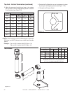
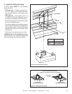
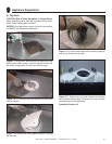
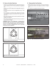
Figure 8.5 Attic Insulation Shield
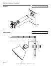
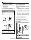
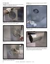
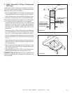
Figure 8.6 Heat Zone Cover Plate
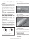
E. Installing the Optional Heat-Zone-Gas Kit
• Remove the knockout from the fi replace and discard it
(see Figure 8.6).
• Center the duct collar around the exposed hole and
attach it to the fi replace with 3 screws. Note: Do this
BEFORE fi nal positioning of fi replace.
• Determine the location for the air register/fan housing
assembly.
Reference the Heat-Zone-Gas kit instructions for the
remaining installation steps.
HEAT-ZONE-GAS
ATTACHES HERE
Vaulted Ceiling Installation
• Remove one shield from box.
NOTICE: Cut previously installed batt insulation to make
room for the attic insulation shield.
• Cut the attic insulation shield (if application is for vaulted
ceiling) to fi t your ceiling pitch. Snip cut edge to recreate
1 in. bend tabs all the way around the bottom.
• Wrap shield around pipe if pipe is already installed in
area to be insulated.
• Match the three holes in each side and fasten with three
screws to form a tube.
• Bend three tabs on the bottom of the shield outward to
allow attachment to the ceiling fi restop.
• Bend the remaining bottom tabs inward 90º to maintain
the air space between the pipe and the shield. Set the
shield on the ceiling fi restop and attach to the fi restop.
• Bend all tabs inward 90º around the top of the shield.
These tabs must be used to prevent blown insulation
from getting between the shield and vent pipe, and to
maintain air space clearance.
BEND ALL TABS INWARD 90°
TO MAINTAIN CLEARANCE
AND PREVENT INSULATION
FROM FALLING INSIDE
INSERT 3
SCREWS
BEND 3 TABS
OUTWARD TO
FASTEN TO CEILING
FIRESTOP-BEND
REMAINING TABS
INWARD 90 DEGREES
TO MAINTAIN
CLEARANCE