


Heatilator • Novus NDV Series • 4055-187 Rev. V • 1/12 19
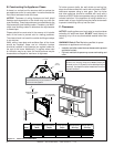
In addition to these framing dimensions, also reference the
following sections:
• Clearances and Mantel Projections (Sections 3.C. and 3.D.)
• Vent Clearances and Framing (Section 6)
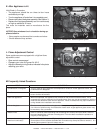
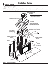
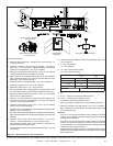
Rear vent
One 45° elbow
Horiz Term
Rear Vent
Two 90° elbows
Horiz Term
Rear Vent
One 90° elbow
Vert Term
Top Vent
One 90° elbow
Horiz Term
No elbows
Horiz Term
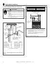
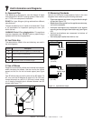
A
A
A
A
A
A
C
B
B
E
F
D
1/2 in. (13 mm) min.
appliance to
combustibles
D
F
1 in. (25 mm)
min. pipe to
combustibles
E
1/2 in. (13 mm)
min. appliance
to combustibles
Alcove
Installation
C
1 in. (25 mm)
min. pipe to
combustibles
G
Drywall
48 in.
(1219 mm)
maximum
ABCDEFG
in.
36 33-1/2 19-5/8 43-3/8 47 53-1/4 37
mm
914 851 498 1102 1194 1353 940
in.
39 35-1/2 19-5/8 43-3/8 47 53-1/4 40
mm
991 902 498 1102 1194 1353 1016
in.
42 37-5/8 19-5/8 43-3/8 47 53-1/4 43
mm
1067 956 498 1102 1194 1353 1092
in.
48 41-7/8 19-5/8 43-3/8 47 53-1/4 49
mm
1219 1064 498 1102 1194 1353 1245
NDV4842
Model
NDV3630
NDV3933
NDV4236
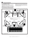
5
5
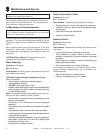
Framing and Clearances
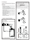
A. Select Appliance Location
When selecting a location for your appliance it is important to
consider the required clearances to walls (see Figure 5.1).
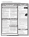
WARNING! Risk of Fire or Burns! Provide adequate
clearance around air openings and for service access.
Due to high temperatures, the appliance should be locat-
ed out of traffi c and away from furniture and draperies.
NOTICE: Illustrations refl ect typical installations and are
FOR DESIGN PURPOSES ONLY. Illustrations/diagrams
are not drawn to scale. Actual installation may vary due to
individual design preference.
Figure 5.1 Appliance Locations