


Heatilator • Novus NDV Series • 4055-187 Rev. V • 1/12 17
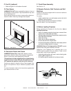
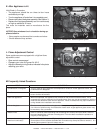
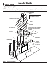
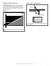
A. Typical Appliance System
NOTICE: Illustrations and photos refl ect typical installations and are for design purposes only. Illustrations/diagrams are not
drawn to scale. Actual product may vary from pictures in manual
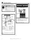
CEILING FIRESTOP
ON FLOOR OF ATTIC
(SECTION 8)
VERTICAL TERMINATION CAP
(SECTION 10)
HORIZONTAL TERMINATION CAP
(SECTION 10)
VENT PIPE PENETRATES ROOF
PREFERABLY WITHOUT AFFECTING
ROOF RAFTERS
FRAMING HEADED OFF
IN CEILING JOISTS
(SECTION 8)
GAS LINE
(SECTION 11)
MANTEL AND MANTEL LEG
(SECTION 5 & 13)
SURROUND (SECTION 14)
HEARTH EXTENSION
(Section 13)
VENT PIPE (SECTION 8)
OPTIONAL
WALL SWITCH
(Section 12)
ATTIC INSULATION SHIELD (NOT SHOWN) MUST
BE USED HERE TO KEEP INSULATION AWAY
FROM VENT PIPE IF ATTIC IS INSULATED
(SECTION 8)
STORM COLLAR
(SECTION 10)
NON-COMBUSTIBLE ROOF FLASHING
MAINTAINS MINIMUM CLEARANCE
AROUND PIPE (SECTION 10)
FRAMING/HEADER
(SECTION 5)
NOTE: An installation will have either a
vertical termination or a horizontal
termination. It will not have both (as
shown).
Figure 4.1 Typical Appliance System
4
4
Getting Started
Installer Guide