


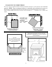
FREESTANDING STOVE INSTALLATION REQUIREMENTS
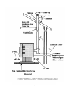
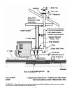
Horizontal Exhaust Termination:
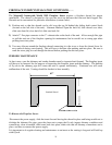
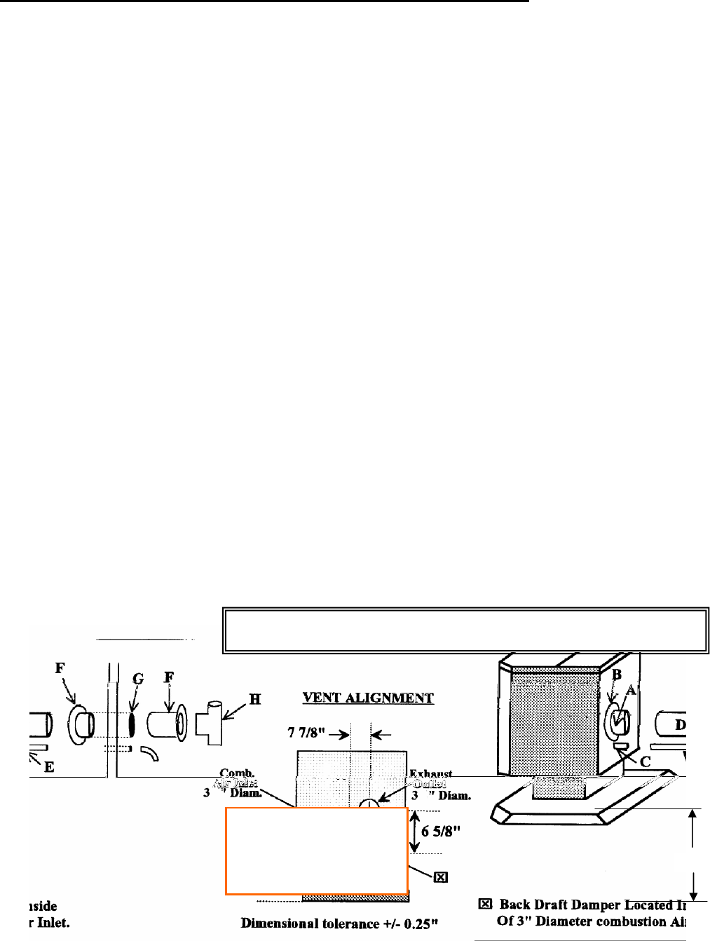
1) Locate proper position for the type “PL” wall thimble (F). Use a saber saw or key- hole saw to cut a
2) 7 1/4-inch diameter hole through the wall (G) for a 3-inch pipe. For a 4-inch pipe, cut an 8 1/4-inch
hole. Install the wall thimble in the hole. The size of hole opening will vary with brand of wall
thimble.
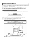
3) Position stove approximately 12” from the wall on the noncombustible floor pad. Push the type “PL”
pipe (D) through the wall thimble (F). Squeeze a bead of high temperature RTV silicone sealer (A)
around the outside of the 3” diameter exhaust pipe approximately ½” from the stove back panel (B).
Firmly push on a section of type “PL” pipe (D) until the inner pipe liner pushes up against the bead of
RTV sealer. Don’t seal the entire 3” diameter pipe as you will not be able to disassemble the pipe at a
later date. The bead of silicone will act as a gasket right on the end of the 3” pipe (D). Alternate
Method: An approved type “PL” connector back clamp may be used to allow easy disconnect for
maintenance. (The RTV sealant must be used in mobile home installation)
4) Push stove with pipe attached towards wall. Pipe (D) will go through the wall thimble (F). Be careful
not to dislodge the thimble. Position stove not closer than 1” to the wall.
5) NOTE: Make sure that you leave enough clearance between the wall and the back of the unit so that
when you open the hopper lid it will not hit pictures on the back wall. It is recommended that you
leave 4-6” between the wall and the back for the unit for easy access.
6) Install type “PL” termination cap (H) with rodent screen cap (optional) on outside end of pipe. Note:
The end of the exhaust pipe must extend a minimum of 12 inches from the outside of the building.
Rodent screen cannot be less that 3/8” opening mesh.
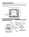
7) If installing with combustion air from outside, cut a separate hole through the wall for the fresh air
tube (E). This tube must be 3” minimum diameter steel only. Connect outside air pipe inlet on stove
(C). This tube must be terminated with a 90 degree elbow or hood. Care must be taken not to
interfere with the operation of the combustion-air back draft damper. Always make sure that it moves
freely.
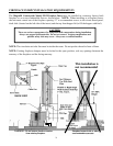
NOTE: Always check dimensions on unit before cutting hole in wall.
NOTE: air intake must be 2-
3 feet away from the exhaust
outlet and must be 2 feet
lower.
17”
18