


Page 7For technical questions, please call 1-800-444-3353.SKU 3914
ASSEMBLY
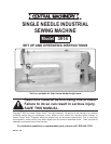
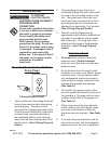
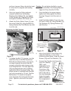
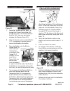
Sewing Machine
Motor
Power
Switch
Knee Lifting Arm
for Presser Foot
Table Stand and
Top (not provided)
Figure 1
The assembly instructions describe mounting
the Single-Needle Sewing Machine (Model
03914) to the Table Stand (Model 03929), not
included. In order to complete this procedure,
you must rst purchase and assemble the
Table Stand Kit (Model 03929).
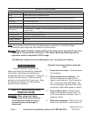
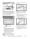
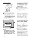
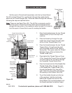
Installing the Oil Pan and Sewing Machine
to the Tabletop of Industrial Sewing
Machine Table (SKU 3929 - sold separately)
Figure 2
Rubber Cushions (24g)
Rubber Cushions (24g)
Rubber Pads (23g)
Rubber Pads (23g)
Corner Rests
Oil Pan (1g) hole
in Tabletop (30)
(Operator Side of Table)
1. Working in the rectangular hole of the
Tabletop where the Oil Pan (1g) will sit:
Place the Rubber Cushions (24g) on
the operator-side corner rests, and the
Rubber Pads (23g) on the hinge-side
corner rests. Secure with two Tacks
(25g) in each Pad or Cushion.
Note: The Rubber Pads (23g) are optional.
They may be omitted, or used under the
Rubber Cushions (24g) to adjust the tilt
of the machine, depending on the user’s
preference.
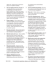
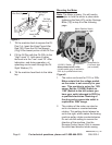
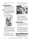
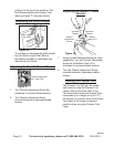
Figure 3
Back of
Sewing
Machine
Hinge (1h)
Hinge Indentations in Tabletop
Oil Pan (1g)
2. Seat the Oil Pan (1g) on the Rubber
Pads and Cushions in the Tabletop
opening.
Insert the Hinge Cushions (2h) into the 3.
tabletop, securing them with two Tacks
(25g) in each Hinge Cushion.
Insert the Hinges (1h) into the holes in 4.
the back of the Sewing Machine.
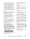
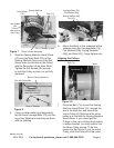
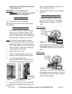
Machine Rest
Pin (19h)
Figure 4
5. Insert the Machine Rest Pin (19h) in the
hole provided in the table stand.
Carefully place the machine, hinge side 6.
rst, into the Rubber Hinge Plates and
over the Oil Pan.
REV 07f, 10b