


Page 19For technical questions, please call 1-800-444-3353.SKU 3914
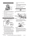
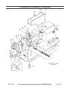
Adjusting the Presser Bar Height
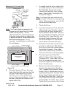
Figure 34
Rubber Plug
(37a)
&
Presser Bar
Set Screw
(32d)
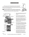
1. Remove and set aside the Rubber Plug
(37a), and loosen the Presser Bar Set
Screw (32d).
Manually adjust the Presser Bar height, 2.
and the angle of the Presser Foot.
After adjusting, securely tighten the Set 3.
Screw and replace the Rubber Plug.
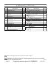
Adjusting the Thread Take-up Stroke
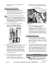
Figure 35
Thread Guide (35a)
Thread Guide Bolt (36a)
Normal
Setting
Thread Take-up
Spring (9a)
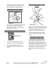
1. To adjust the thread take-up stroke,
loosen the Thread Guide Bolt (36a) and
slide the Thread Guide (35a) to the right
or left as described following:
When sewing heavy weight materials, a.
move the Thread Guide (35a) to the left
to increase the length of thread pulled
out by the Thread Take-up Spring (9a).
When sewing lightweight materials, b.
move the Thread Guide (35a) to the
right to decrease the length of thread
pulled out by the Thread Take-up
Spring.
The normal setting is when the marker c.
on the Thread Guide is aligned with the
center of the Bolt.
Tighten the Thread Guide Bolt after 2.
adjusting the Thread Guide.
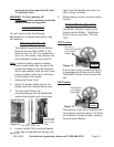
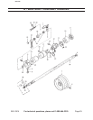
Adjusting the Height of the Knee
Lifter
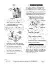
The standard height of the Presser Foot
lifted using the Knee Lifter is 0.39 inch (10
mm).
Figure 36
Nut (8g)
Stud (7g)
Knee Press
Lifter Crank
(15g)
1. To adjust the Presser Foot lift up to
0.5 inch (13 mm), adjust the Nut (8g)
placement on the Stud (7g), on the Knee
Press Lifter Crank (15g).
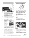
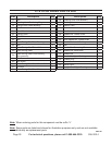
Figure 37
Needle Bar
Thread Guide
(24c)
Presser Foot
(9d)
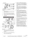
2. When the Presser Foot lift is adjusted
over 0.39 inch (10 mm), be sure that the
Needle Bar Thread Guide (24c) does not
hit the Presser Foot (9d). This can be
manually checked by turning the Hand
Wheel (7b).
REV 10b