


Page 11For technical questions, please call 1-800-444-3353.SKU 3914
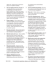
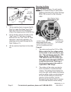
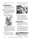
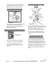
Mounting the Thread Stand
Figure 13
Thread Hanger
(28i)
Upper Spool
Rest Rod
(30i)
Lower Spool
Rest Rod
(36i)
Column Pipe
Connector (33i)
Spool
Pins
(40i)
Note: The Thread Stand is designed to be
mounted on the Table Stand Kit (Model
03929-sold separately). Unless
indicated otherwise, all parts referred to
in this set of instructions are listed in the
I - Bobbin Winder & Thread Stand Unit
Parts List and Diagram. During
assembly, it will be helpful to refer to that
list and diagram.
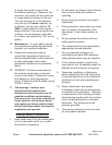
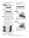
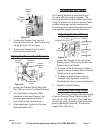
Legs
Possible ON/OFF Control Box location
Pre-drilled Engine
mounting holes
Machine Rest Pin (19h) hole
Thread Stand hole
Pulley Belt Slot
Sewing Machine
Opening
Back of Tabletop
Front of Tabletop
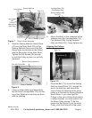
Figure 14
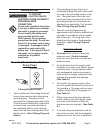
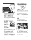
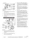
6. Place the Washer (37i) onto the Lower
Spool Rest Rod (36i) and insert the Rod
into the Thread Stand Hole in the far
right back corner of the tabletop (see
above). Place another Washer (37i) over
the end of the Rod, and thread on and
tighten a Nut (38i).
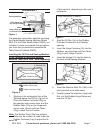
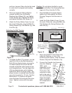
If needed, bend the Spool Support (46i) 7.
so it slides easily over the Lower Spool
Rest Rod (36i), then slide it over the
Lower Spool Rest Rod, about halfway
down. Insert a Bolt (31i) and Nut (47i)
through the Support.
Note: The Support has tabs that hold onto
the corners of the Nut to make tightening
easier. When assembling, place the Nut
on the side with these tabs.
Tighten the Screw.8.
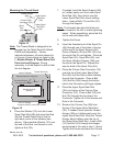
Insert the threaded end of the Spool Pin 9.
(40i) through one of the holes in the top
of the arm of the Spool Support (46i).
Place a Washer (32i) and Nut (35i) over
the end of the Pin and tighten. Place the
Spool Rest (41i), Spool Mat (42i), and
the Spool Vibration Stopper (39i) over
the end of the Spool Pin. Repeat this
step for both of the Spool Pins (40i).
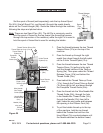
Place the Column Pipe Connector (33i) 10.
over the top of the Lower Spool Rest
Rod (36i) until the Rod is about halfway
through the Connector. Place a Bolt
(34i) and Nut (35i) through the bottom
hole in the Connector and nger-tighten.
Place the Upper Spool Rest Rod 11.
(30i) into the top of the Column Pipe
Connector (33i). Place a Bolt (34i) and
Nut (35i) through the top hole in the
Connector. Tighten all of the Screws and
Nuts in the Connector.
Remove the Column Cap (29i) from 12.
the top of the Upper Spool Rest Rod
(30i). If needed, bend open the Thread
Hanger (28i) so it slides easily over the
Upper Spool Rest Rod. Slide the Thread
Hanger about halfway over the top of
the Upper Spool Rest Rod. Insert a Bolt
(31i) and Nut (47i) through the Hanger
as explained in the note in step 7, above.
Tighten the Screw and place the Column
REV 04c, 05d, 10b