


Hampton
®
H25-1 Direct Vent Freestanding Gas Stove
33
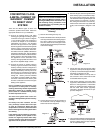
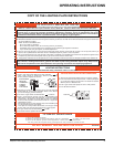
CAUTION
Do not connect the
millivolt remote control wires
to the 120V wires.
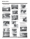
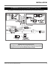
3) Install 3 AAA alkaline batteries in transmitter
and 4 AA alkaline batteries in the receiver.
Install the receiver and its cover in the wall.
Switch the remote receiver to "remote"
mode. The remote control is now ready for
operation.
REMOTE CONTROL
Use the Hampton
®
Remote Control Kit approved
for this unit. Use of other systems may void
your warranty.
The remote control kit comes with a hand held
transmitter, a receiver and a wall mounting
plate.
1) Choose a convenient location on the wall
to install the receiver and the receptacle
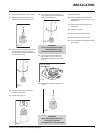
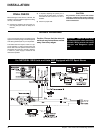
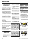
WALL THERMOSTAT
A wall thermostat may be installed if desired.
Connect the wires as per the wiring diagrams.
Note that the wires are connected to the "TH"
on the gas valve. Use table below to determine
the maximum wire length:
Note: Preferable if the thermostat is installed
on an interior wall.
Hampton
®
offers an optional programmable
thermostat but any 250-750 millivolt rated non-
anticipator type thermostat that is CSA, ULC or
UL approved may be used.
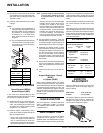
14 GA.
16 GA.
18 GA.
20 GA.
22 GA.
50 Ft.
32 Ft.
20 Ft.
12 Ft.
9 Ft.
Recommended Maximum Lead Length
(Two-Wire) When Using Wall
Thermostat (CP-2 System)
Wire Size Max. Length
Thermostat Wire Table
CAUTION
Do not connect the millivolt
wall thermostat wires
to the 120V wires.
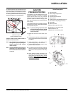
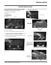
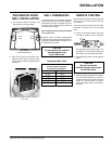
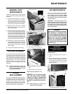
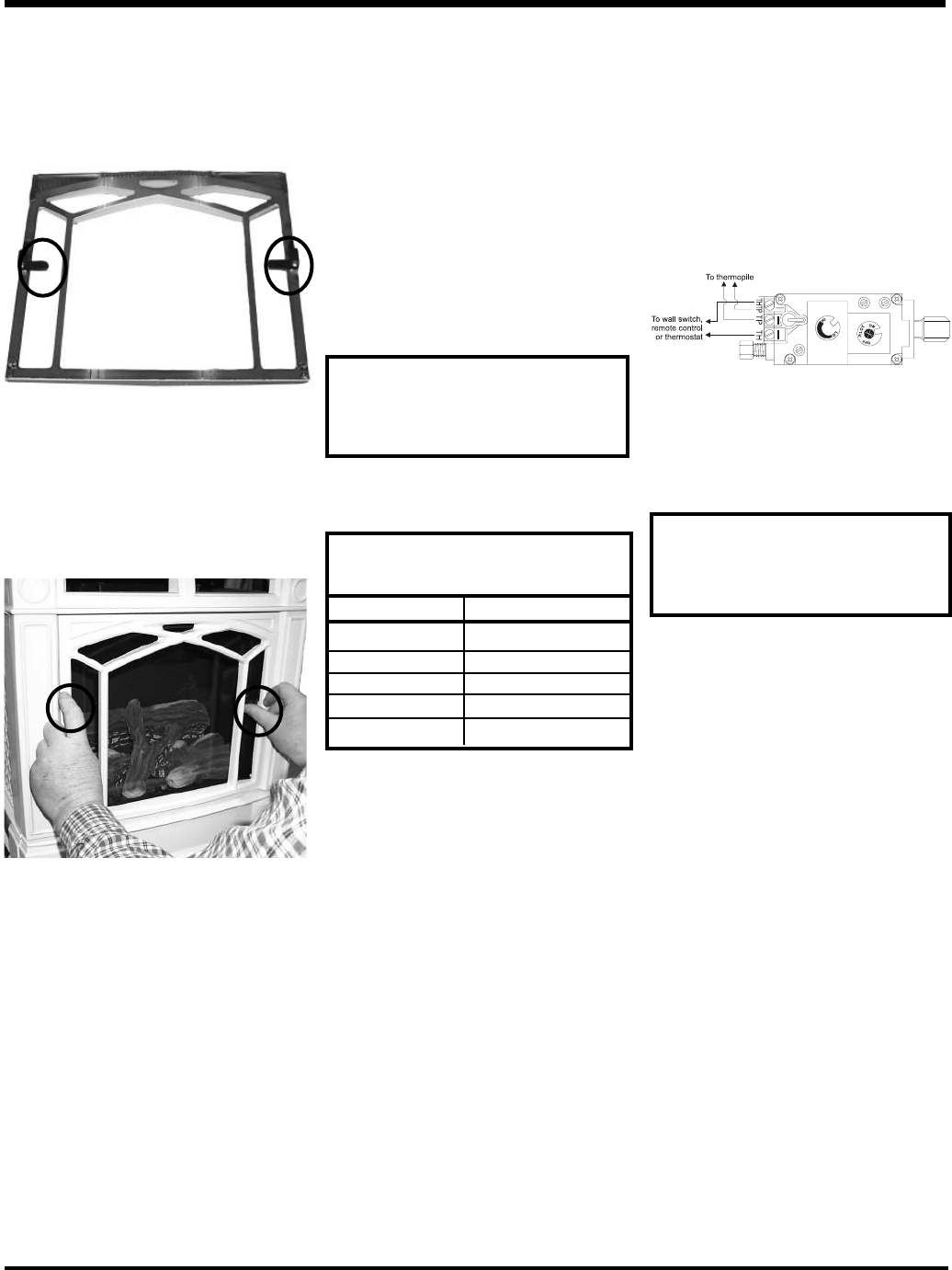
Rear View of
Decorative Door Grill
Grill
Latch
DECORATIVE DOOR
GRILL INSTALLATION
1) Turn the Grill Latches on the Rear of the
Door Grill as per the photo below.
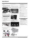
INSTALLATION
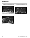
Grill
Latch
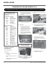
2) Place the Door Grill into the Cast Front.
Secure the Door Grill by turning the Grill
Latches inward, between the glass and the
Cast Front.
Turn the Grill Latches inward to secure the
Door Grill.
box (protection from extreme heat is very
important). Run wires from the fi replace to
that location, use Thermostat Wire Table.
2) Connect the wires as per the wiring diagram
below.