


Hampton
®
H25-1 Direct Vent Freestanding Gas Stove
27
INSTALLATION
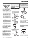
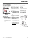
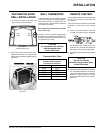
GAS PIPE
PRESSURE TESTING
The appliance must be isolated from the gas
supply piping system by closing its individual
manual shut-off valve during any pressure
testing of the gas supply piping system at test
pressures equal to or less than 1/2 psig. (3.45
kPa). Disconnect piping from valve at pressures
over 1/2 psig.
The manifold pressure is controlled by a regulator
built into the gas control, and should be checked
at the pressure test point.
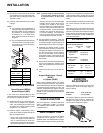
Note: To properly check gas pressure, both
inlet and manifold pressures should
be checked using the valve pressure
ports on the valve.
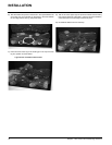
1) Make sure the valve is in the "OFF" posi-
tion.
2) Loosen the "IN" and/or "OUT" pressure tap(s),
turning counterclockwise with a 1/8" wide fl at
screwdriver.
3) Attach manometer to "IN" and/or "OUT"
pressure tap(s) using a 5/16" ID hose.
4) Light the pilot and turn the valve to "ON"
position. Read manometer.
5) The pressure check should be carried out
with the unit burning and the setting should
be within the limits specifi ed on the safety
label.
6) When fi nished reading manometer, turn
off the gas valve, disconnect the hose and
tighten the screw (clockwise) with a 1/8" fl at
screwdriver. Note: Screw should be snug,
but do not over tighten
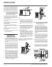
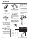
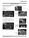
To adjust the aeration: use the allen key to turn
the turning gear which will adjust the air shutter.
Open the air shutter for a blue fl ame or close it
for a more yellow fl ame. This adjustment is per-
formed by a qualifi ed installer. The factory setting
should be suffi cient for most installations.
Clockwise to open,
counter-clockwise to close.
Caution: Carbon will be produced if the air
shutter is closed too much.
Note: Any damage due to carboning re-
sulting from improperly setting the
aeration controls is NOT covered
under warranty.
Note: Aeration Adjustment should only be
performed by an authorized Hamp-
ton
®
Installer at the time of installation
or service.
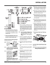
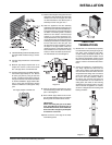
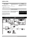
Valve Description
1) Gas on/off knob
2) Manual high/low adjustment
3) Pilot Adjustment
4) Thermocouple Connection
5) Main Operator
6) Outlet Pressure Tap (Manifold Pressure)
7) Inlet Pressure Tap (Supply Pressure)
8) Pilot Outlet
9) Main Gas Outlet
10) Flange Securing Screw Holes
11) Alternative TC Connection Point
12) Thermoelectric Unit
13) Additional Valve Mounting Hole