


Hampton
®
H25-1 Direct Vent Freestanding Gas Stove
19
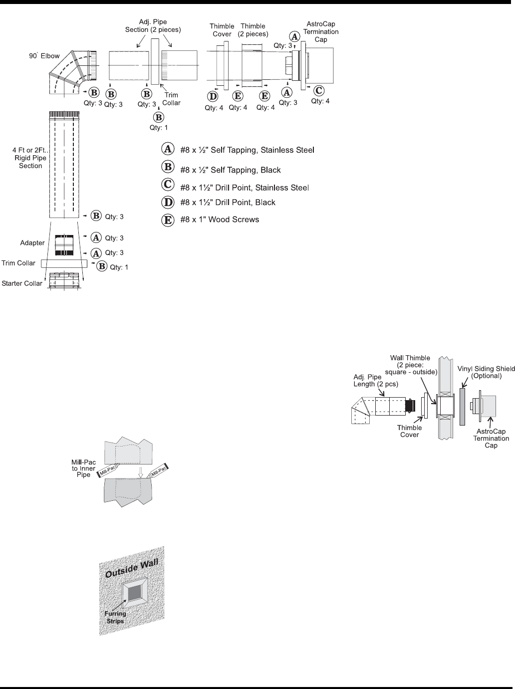
INSTALLATION
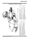
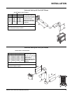
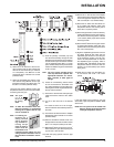
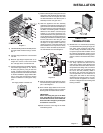
Note: The pipe
seam
should
be facing
down.
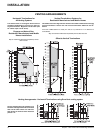
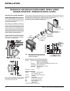
Note: To make the installation more aes-
thetically pleasing, we recommend
framing out a square that the cap
can be mounted on.
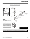
Note: If installing ter-
mination on a
siding covered
wall, a vinyl sid-
ing standoff or
furring strips
must be used to
ensure that the
termination is not
recessed into the siding. For vinyl
siding standoff installation refer to
the Dura-Vent Termination instruc-
tions.
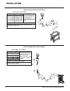
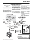
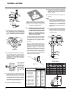
3) Attach the 4" dia. fl ex liner to the vent ter-
minal ensuring that the fl ex overlaps the
collar of the vent terminal by a minimum
of 1-3/8"(35mm). Use Mill-Pac to seal
and secure with 3 of the #8 x 1/2" screws
(stainless steel).
4) Attach the adjustable pipe section to the
vent terminal using Mill-Pac and/or high
temperature silicone and attach with 3 of
the #8 x 1/2" screws (stainless steel).
Hint: Apply the sealant (Mill-Pac and/or high
temperature silicone) to the outer pipe before
connecting the inner pipe.
5) Slide the partially connected pipe and
vent terminal assembly through the wall
thimbles (from the exterior into the interior)
and secure the cap to the exterior wall with
4 of the supplied screws (#8 x 1-1/2" drill
point, stainless steel). Note: pilot holes will
need to be drilled through the wall thimble
on all 4 corners.
Note: The four screws provided for the
vent cap should be replaced with
appropriate fasteners for stucco,
brick, concrete, or other types of
sidings.
6) A bead of non-hardening mastic should
be run around both the termination and
vinyl siding standoff to prevent water from
entering and to make a tight seal between
the cap and the standoff.
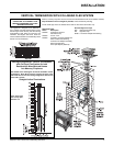
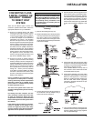
7) Stretch the 4" dia. fl ex liner out fully and get
a trial fi t of the liner onto the 4" dia. starter
collar.
8) Cut the 4" dia. fl ex liner to the desired
size.
Hint: leave an extra 12" to 16" of length,
this will make the fi nal assembly easier to
work with.
9) Secure the 4" dia. fl ex liner to the 4" adapter
with Mill-Pac and 3 of the #8 x 1/2" screws
(stainless steel).
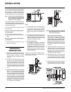
10) Slide the decorative Thimble Cover over
the pipe sections and secure with 4 screws
(#8 x 1-1/2" drill point, black) to the wall.
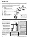
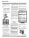
11) Slide the 90
o
elbow (crimp end up), the 45
o
elbow and the 4 ft. pipe section (crimp end
up) over the 4" dia. fl ex liner.
12) Install the spring spacers onto the pipe
sections.
13) Secure the 4" dia. fl ex liner with adapter
onto the stove collar. Put a bead of Mill-Pac
around the appliance adapter and secure
with 3 screws (#8 x 1/2, stainless steel).
14) Attach the 45
o
elbow onto the starter col-
lar by sealing with Mill-Pac and/or high
temperature silicone and securing with 3
of the #8 x 1/2" (black) screws.
15) Attach the pipe section to the 45
o
elbow by
sealing with Mill-Pac and/or high tempera-
ture silicone and securing with 3 of the #8
x 1/2" screws (black). Pipe seams should
be facing the wall.
16) Attach the 90
o
elbow onto the pipe section
by sealing with Mill-Pac and/or high tem-
perature silicone and securing with 3 of the
#8 x 1/2" screws (black).
17) Slide the adjustable pipe section onto the
90
o
elbow. Slide the trim collar over the
adjustable pipe sections to cover the joint
of the telescopic section.) The fl ex may
have to be compressed back in order for
the adjustable pipe to properly mate to
the elbow. Seal with Mill-Pac and/or high
temperature silicone and secure with 3 of
the #8 x 1/2" screws (black). Pipe seams
facing down.
18) Install the trim collar over the starter col-
lar and secure with a #8 x 1/2" screw
(black).
If the pipe needs to be touched up, use only
Stove Brite High Temperature Metallic Black
Stove Paint.
NOTE: All inner joints must be sealed with
Mill-Pac. All outer joints may be sealed
with high temperature silicone.