


22
Hampton
®
H25-1 Direct Vent Freestanding Gas Stove
INSTALLATION
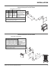
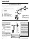
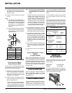
You will require the following components with
your new Direct Vent Freestanding Gas Stove.
Please review your product to make sure you
have everything you need. In the event that
you are missing any part, contact your dealer.
Note: These are the minimum pieces re-
quired. Other parts may be required
for your particular installation. See
above for a list of vent parts.
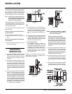
If installing termination on a siding covered wall,
a vinyl siding standoff or furring strips can be
used in order to ensure that the termination is
not recessed into siding.
The vinyl siding standoff is required for walls
with vinyl siding.
Minimum components for a Dura-Vent Hori-
zontal Installation:
A) Dura-Vent Horizontal Termination Kit
B) Wall Thimble (required for combustible
walls)
Minimum components for a Dura-Vent Verti-
cal Termination:
D) Dura-Vent Vertical Termination Kit. See
above for pipe lengths.
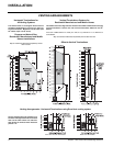
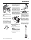
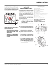
Diagram 2a
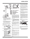
HORIZONTAL
TERMINATIONS
1) Set the unit in its desired location. Check to
determine if wall studs are in the way when
the venting system is attached. If this is the
case, you may want to adjust the location
of the unit.
2) Assemble the desired combination of pipe
and elbow to the appliance adapter with
pipe seams oriented down. Offset the pipe
seams as double seams in one place will
cause the outer pipe to take an oval shape.
Kit comes complete with 18" of straight vent
- 6-5/8" dia. black outer pipe and 4" dia. inner
vent.
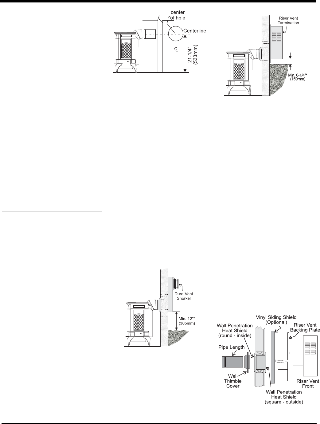
3) With the pipe attached to the stove, slide the
stove into its correct location, and mark the
wall for a 9-1/2" (inside dimensions) round
hole. The center of the round hole should line
up with the centerline of the horizontal pipe,
as shown in diagram 1. Cut and frame the
9-1/2 round hole in the exterior wall where
the vent will be terminated. If the wall being
penetrated is constructed of non-combusti-
ble material, i.e. masonry block or concrete,
a 7" diameter hole is acceptable.
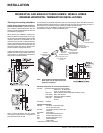
Note:
a) The horizontal run of vent should have a
1/4 inch rise for every 1 foot of run towards
the termination. Never allow the vent to run
downward. This could cause high tempera-
tures and may present the possibility of a
fi re.
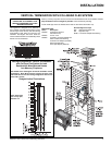
b) The location of the horizontal vent termination
on an exterior wall must meet all local and
national building codes, and must not be
blocked or obstructed. Refer to the "Exterior
Vent Terminal Locations" section.
c) Snorkel Terminations:
For installations requiring a vertical rise
on the exterior of the building, 14-inch and
36-inch tall Snorkel Terminations as shown
in Diagram 2 are available, as well as the
standard Riser Vent. Follow the same in-
stallation procedures as used for standard
Horizontal Termination. NEVER install the
snorkel upside down.
Diagram 1
*Diagram 2a: As specifi ed in CGA B149 Instal-
lation Code. Local codes or regulations may
require different clearances.
Diagram 2b
NOTE: For Snorkel terminations in ABOVE
grade installations, follow national or
local code requirements.
Below Grade Snorkel Installation
If the Snorkel Termination must be installed
below grade, i.e. basement application,
proper drainage must be provided to prevent
water from entering the Snorkel Termination.
Refer to Dura-Vent Installation instructions
for details.. Do not attempt to enclose the
Snorkel within the wall, or any other type of
enclosure.
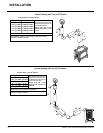
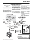
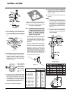
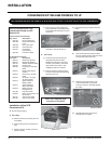
4) Install wall penetration heat shield in the
center of the 9-1/2" round hole and attach
with wood screws. The four wood screws
provided should be replaced with appropri-
ate fasteners for stucco, brick, concrete, or
other types of sidings. Diagram 3.
5) If installing termination on a siding covered
wall, a vinyl siding standoff or furring strips
must be used to ensure that the termination
is not recessed into the siding. Diagram
3.
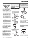
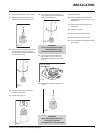
6) Take the Riser Vent terminal and separate
the Backing Plate from the Riser Vent Front
by removing 8 screws as shown in diagram
4.
Diagram 3