


10
Hampton
®
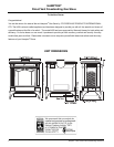
H25-1 Direct Vent Freestanding Gas Stove
INSTALLATION
PRECAUTIONS
These venting systems are engineered products
that have been designed and tested for use
with the H25-NG1, and H25-LP1. The warranty
will be voided and serious fi re, health or other
safety hazards may result from any of the fol-
lowing actions:
1) Installation of any damaged Direct Vent
component
2) Unauthorized modifi cation of the Direct Vent
System
3) Installation of any component part not manu-
factured or approved by Simpson Dura-Vent
or FPI Fireplace Products International
Ltd.
4) Installation other than as instructed by Simp-
son Dura-Vent and FPI Fireplace Products
International Ltd.
Warning: Always maintain required
clearances (air spaces) to nearby
combustibles to prevent a fire
hazard. Do not fi ll air spaces with
insulation.
Be sure to check the vent termination clearance
requirements from decks, windows, soffi ts,
gas regulators, air supply inlets and public
walkways as specifi ed in the "Exterior Vent
Terminal Locations" section and in your local
building codes.
The gas appliance and vent system must be
vented directly to the outside of the building,
and never be attached to a chimney serving
a separate solid fuel or gas-burning appli-
ance. Each direct vent gas appliance must use
it's own separate vent system. Common vent
systems are prohibited.
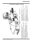
VENTING
INTRODUCTION
The Horizontal Termination Kit and the Simpson
Dura-Vent Direct Vent System Model DV-GS
venting systems, in combination with the Direct
Vent Freestanding Gas Stoves, H25-NG1, and
H25-LP1, have been tested and listed as direct
vent heater systems by Warnock Hersey.
These units use the "balanced fl ue" technology
Co-Axial system. The inner liner vents products
of combustion to the outside while the outer pipe
draws outside combustion air into the combus-
tion chamber thereby eliminating the need to
use heated room air for combustion and losing
warm room air up the chimney.
Note: These fl ue pipes must not be
connected to any other appliance.
The gas appliance and vent system must be
vented directly to the outside of the building,
and never be attached to a chimney serving a
separate solid fuel or gas burning appliance.
Each direct vent gas appliance must use it's own
separate vent system. Common vent systems
are prohibited.
IMPORTANT
Read all instructions carefully before starting
the installation. Failure to follow these instruc-
tions may create a fi re or other safety hazard,
and will void the warranty. Be sure to check the
venting and clearance to combustible require-
ments. Consult your local building codes before
beginning installation.
The location of the termination cap must con-
form to the requirements in the "Exterior Vent
Terminal Locations" section.
SAFETY PRECAUTIONS
FOR THE INSTALLER
1) Wear gloves and safety glasses for protec-
tion.
2) Exercise extreme caution when using lad-
ders or on roof tops.
3) Be aware of electrical wiring locations in
walls and ceilings.
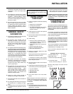
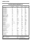
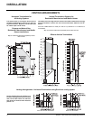
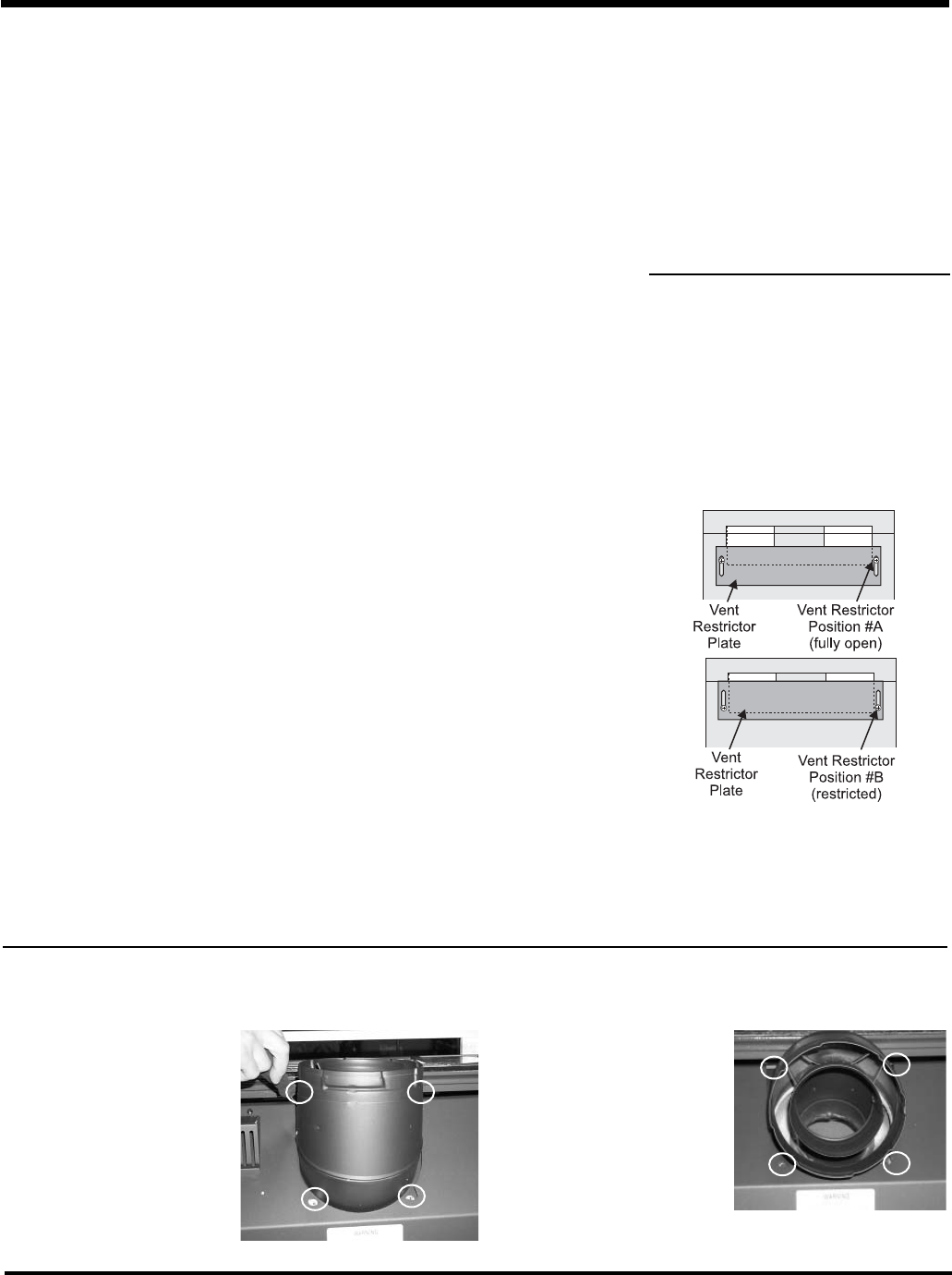
VENT RESTRICTOR
POSITION
To set the Vent restriction as indicated in the
diagrams in "Venting Arrangements" section,
simply loosen the screws and push the vent
restrictor plate to the correct position. Tighten
the screws.
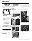
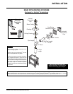
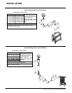
INSTALLATION
ROTATING 45
O
ELBOW
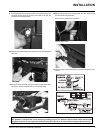
1) Remove all 4 screws that secure
the elbow to the unit using a 1/4"
magnetic nut driver.
2) Rotate the elbow 180
o
3) Secure the elbow by securing
it with the 4 screws.
Remove all 4 screws
and washers