


26
Hampton
®
H25-1 Direct Vent Freestanding Gas Stove
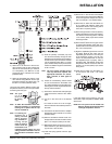
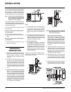
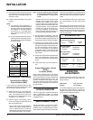
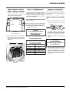
AERATION
ADJUSTMENT
The burner aeration is factory set but may need
adjusting due to either the local gas supply, air
supply or altitude.
Natural Gas 3-16" (4.76 mm)
Propane 1/4" (6.4 mm)
The aeration adjustment gears are located on
the right side of the burner box. Remove the
Hampton
®
Logo plate on the right side of the
unit to access the adjustment gears.
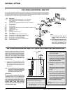
SYSTEM DATA - H25
For 0 to 4500 feet altitude
Burner Inlet Orifi ce Sizes:
Natural Gas Propane
Burner #42 #54
Max. Input Rating
- Natural Gas 25,000 Btu/h
- Propane 23,000 Btu/h
Min. Input Rating
- Natural Gas 12,500 Btu/h
- Propane 11,500 Btu/h
Supply Pressure
Natural Gas min. 5.0" w.c.
Propane min. 12.0" w.c.
Manifold Pressure
Natural Gas 3.8" +/- 0.2" w.c.
Propane 11" +/- 0.2" w.c.
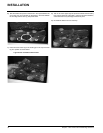
Note: If you are using a 6" square support
you may fi nd it diffi cult to screw it
in place because it is fairly small
inside.
Simpson Dura-Vent has provided angle
brackets with this support which can be
screwed to the outside of the support
box and nailed to surrounding framing as
required. Use a minimum of four #8 x 1/2"
screws per bracket. In some cases these
brackets may need to be trimmed (e.g.:
to fi t under a fl ashing). Place the Finish
Collar around the support and fasten it to
the ceiling using the screws provided.
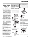
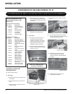
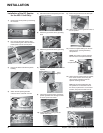
3) Use appropriate roof fl ashing. Place the
fl ashing under the upper shingles and on top
of the lower shingles approximately half of
the fl ashing should be under the shingles.
4) Assemble the desired lengths of Black
Pipe and Elbows necessary to reach from
the appliance adapter up through the sup-
port box and fl ashing to proper height as
per Dia. 12, local codes or in the "Venting
Arrangment" section. Ensure that all pipe
and elbow connections are in their fully twist
lock position.
5) Ensure vent is vertical and secure fl ashing to
the roof with roofi ng nails. Slide the storm
collar over the pipe section and seal with a
mastic.
6) Twist lock the vent cap on to the last sec-
tion.
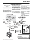
Support Extensions - Round
(RDSE)
or Square (SQSE)
Steep pitched cathedral ceilings may require
the use of a support extension. This piece fi ts
down inside the support and can be adjusted to
increase the support's length by up to 22". The
extension is attached to the support using the
eight metal screws provided. Be sure there is
at least a 2 inch overlap where the extension
joins the support.
HIGH ELEVATION
This unit is approved in Canada for altitude to
4500 ft. (CAN/CGA-2.17-M91). For Natural
Gas installations above 4500 ft. follow current
CAN/CGA-B149.1.
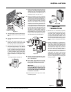
GAS CONNECTION
The gas connection is a 3/8" NPT 90
o
elbow.
The gas line can be rigid pipe or to make in-
stallation easier, use a listed fl exible connector
and/or copper tubing if allowed by local codes.
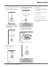
7) Ensure vent is vertical and secure the base
of the fl ashing to the roof with roofi ng rails,
slide storm collar over the pipe section and
seal with a mastic.
8) Install the vertical termination cap by twist
locking it.
Notes:
a) For multistorey vertical installations, a
Ceiling Fire stop (Part # 963) is required
at the second fl oor, and any subsequent
fl oor. Diagram 12. The opening should
be framed to 10 " x 10" inside dimen-
sions, in the same manner as shown in
diagram 9.
b) Any occupied areas above the fi rst fl oor,
including closets and storage spaces,
through which the vertical vent passes,
must be enclosed.
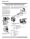
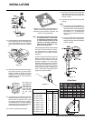
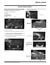
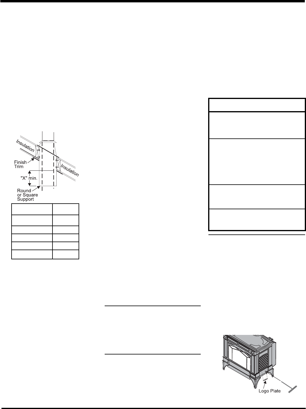
CATHEDRAL CEILINGS
Round Support (RDS) &
Square Support (SQS)
If your home has a cathedral ceiling (no attic
space between the ceiling and the roof), install
the chimney and support as follows.
1) Situate the chimney in a convenient loca-
tion as near as possible to the appliance
outlet. Cut and frame a hole in the roof for
the support. The sides of this hole must be
vertical with 1 1/4" clearance.
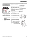
2) Place the support in the opening. Lower it
to the correct height as determined by the
table and diagram below.
Using a level, make sure the support is
vertical. If the support extends above the
roof, cut it fl ush with the top of the roof.
Nail the support to the frame opening using
(8) 3" spiral nails or #8 x 1-1/2" screws.
Slope "X"
0/12 - 2/12 4"
2/12 - 7/12 5-1/2"
7/12 - 12/12 6-3/4"
12/12 - 24/12 7-1/2"
24/12+ 12-1/2"
Since some municipalities have additional local
codes it is always best to consult with your local
authorities and the CAN/CGA B149 installation
codes.
For USA installations follow local codes and/or
the current National Fuel Gas Code, ANSI
Z223.1.
When using copper or fl ex connectors use only
approved fi ttings. Always provide a union so that
gas lines can be easily disconnected for burner
and/or valve servicing. Flare nuts for copper lines
and fl ex connectors are usually considered to
meet this requirement.
INSTALLATION