


30
TELEPHONE (800) 543-1236 OR (850) 575-4144
FAX (850) 575-8950 • E-M AIL: TECHSUP P ORT@GTOINC.COM • WWW.GTOINC.COM
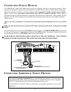
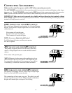
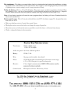
SYSTEM TEST SPECIFICATIONS
Transformer: 120 Vac / 60 Hz input
18 Vac / 40 VA output
10 W solar panel: 18-22 Vdc / 600 mA per hour
Battery: 12 Vdc / 7 Ah
Wire: 16 gauge, multi stranded, direct burial
Motor: 12 Vdc 90 rpm with case hardened gears. The motor current range
is 2.5 to 10 A if the gate is in good working order.
Receiver: 5 Vdc / digital communication. ONLY GTO receivers can be
connected to these terminals.
Control board: Microprocessor driven. Powered by 12 Vdc.
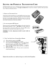
The transformer: Two things can cause failure: the first is shorting the leads during the installation, or letting
the strands touch at the terminal on the control board. The second is a static charge (generally associated with
a lightning storm or power outage); use of a surge protector will help.
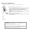
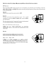
Testing the battery: This is a 12 volt 7 Ah battery. The proper way to test this is to perform a load test. Place
the voltmeter on D.C.; put the red probe on the (+) positive terminal and place the black probe on (-) negative
terminal. Then activate the unit and watch the voltmeter. The drop should not be more than 1 volt.
Note: A loose battery terminal will cause the same symptoms that a bad battery will cause. Terminals should be
secure and corrosion free.
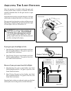
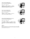
Remote control range: This will vary at each installation. (see FCC disclaimer on page 23), but generally varies
from 50 ft. to 100 ft.
• Make sure that the receiver is located above metal fences.
• Moving the receiver even a few inches can change the range of operation.
• Move the receiver as far from the motor as possible to avoid the chance of electrical interference.
• Check or change the battery in the transmitter.
The GTO, Inc. Technical Service Department is open
Monday – Friday 8:00 A.M. – 5:00 P.M. (Eastern Time)