


29
TROUBLE SHOOTING GUIDE
Maintenance:
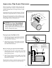
• On all gates weighing 250 lb. or more, routinely grease the ball bearing rollers at least 4 times a year; grease
more frequently if the gates are near a coastal area.
• Keep a few mothballs in the control box to discourage insects from entering it and damaging the control
board.
• Have your gate operator tested monthly and serviced regularly by an experienced technician. The gate
MUST stop and reverse on contact with an obstruction or when an object activates the non-contact sensors.
If these functions are observed to operate improperly, discontinue use and have operator serviced
immediately.
The operator has a 12 Vdc motor with mechanical limit switches.
• To test the motor, put a voltmeter on DC and place the meter leads on the wire connections inside the plastic
cover above the switches. The reading should be at least 11.5 V when the system is active. If it is not, see The
Control Board section
• To test the switches, put the meter on “ohms.” Place the leads on each of the wires on the switch. You should
have an open circuit. Click the switch and you should have .2 ohms. Do this for both switches.
• To test the cable, put the meter on ohms. At one end of the cable place the lead on the green wire, and on the
other end of the cable place the lead on the green wire and the other wires. This should show a maximum of 1.0
ohms on the green wire and nothing on the other wires. Test each wire as you have above. If all have the proper
readings, then this is not the problem.
• Note: Inspect the cable for any signs of any punctures because wires inside the PVC jacket can be shorted and
the cable will still show proper ohms.
The control board: This is a micro processor board. The power that runs the gate is from the battery and recharged,
through the board only, by a 18 volt 40 VA. (2.9 A) transformer.
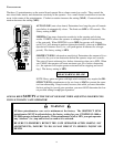
There is one (1) green and one (1) red LED (light emitting diode) on the control board. They are for a quick
reference only. All readings must be measured by a voltmeter!
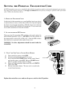
The red light serves two purposes. The first is to aid in storing the personal transmitter code. See “Setting the
Personal Transmitter Code”.
The second is to show the condition of the battery. If it is flashing, see the following section on “ Testing the
battery.” The normal state of this light is on, but dim.
If the red LED is flashing it means that the system may have reached low voltage lockout; the unit does not have
enough voltage to operate the system. One of the following problems may exist:
• Broken or spliced wires from the transformer or solar panel to the control board.
• A transformer or solar panel that has no output voltage.
• Incorrect number of solar panels, or solar panels not properly hooked up.
The green light serves as a quick visual indication that the control board is receiving power from the
transformer.