


16
POWERING THE SYSTEM
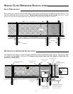
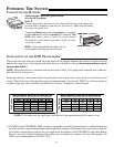
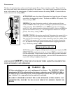
Make sure the control box power switch
is in the OFF position.
ON-OFF
OFF
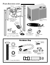
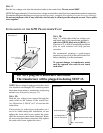
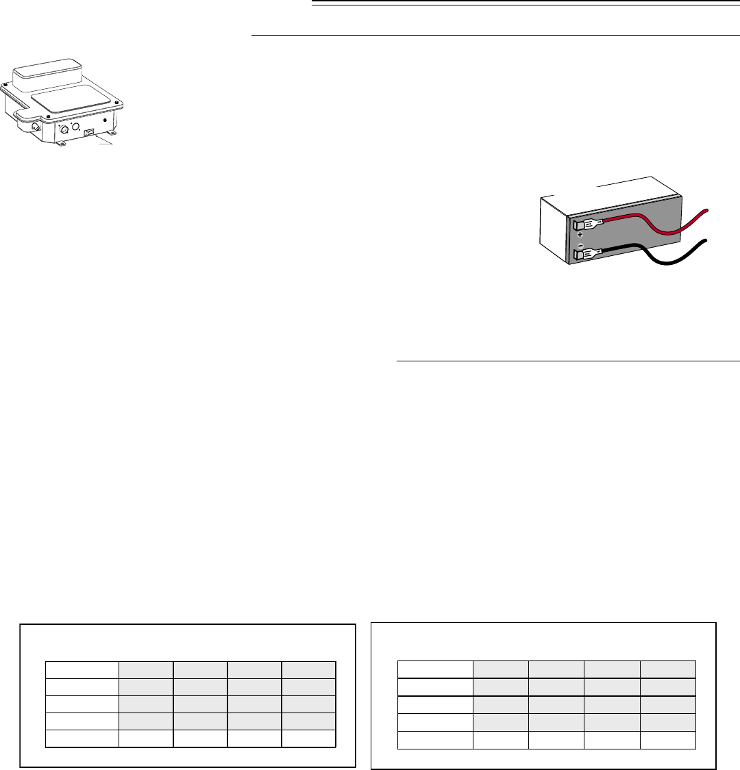
CONNECTING THE BATTERY
INSTALLATION OF THE GTO TRANSFORMER
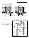
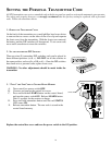
STEP 8
Unscrew and remove the front cover of the control box and slide battery into
position with its terminals to the left (see illustration). Make sure the battery
fits snugly in control box.
Connect the black battery lead to the negative (–) terminal,
and the red battery lead to the positive (+) terminal. DO
NOT allow battery leads to touch the control board!
Touching the control board with battery leads can short
circuit the system!
HINT: a dab of household petroleum jelly on
each terminal will help prevent corrosion.
RED WIRE to positive (+)
BLACK WIRE
to negative (–)
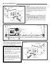
Choose the electrical outlet into which the transformer will be plugged. Measure the distance from the electrical
outlet to the control box, following the path where the low voltage wire will run
(the maximum distance can be
no more than 1000 ft.).
NOTE:
Transformer must be connected with no more than 1000 ft. of 16 gauge multi-stranded, dual conductor,
direct burial low voltage wire.
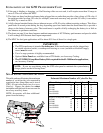
Predicting the exact maximum number of operational cycles at peak load is more of an art form than an exact
science. The charts below illustrate the average maximum number of cycles (the “MNC”) in a 24 hour period on
a typical single gate, and is installed such that the motor draws 10 amperes to move the gate.
1) The MNC for the GTO/PRO SL-2000 is roughly comparable to most AC powered operators, and the transformer
provided with this operator should handle most high traffic situations. If the battery does not seem to be able to
provide the constant charge required for your application, the addition of the GTO/PRO 24 Amp Hour Battery
Kit (see Accessoy Catalog) should provide ample power to handle any situation. For more information, call
GTO’s service department at 1-800-543-1236.
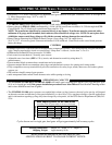
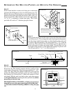
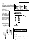
Gate Weight
Gate Opening
Gate Capacity Chart for SL-1000 Series
(estimated number of cycles based on use with a transformer)
20 ft.
16 ft.
12 ft.
8 ft.
120
140
160
180
200 lb.
110
130
150
170
300 lb.
100
120
140
160
400 lb.
90
110
130
150
500 lb.
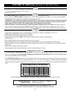
Gate Weight
Gate Opening
Gate Capacity Chart for SL-2000 Series
(estimated number of cycles based on use with a transformer)
20 ft.
16 ft.
12 ft.
8 ft.
80
100
120
140
400 lb.
70
90
110
130
600 lb.
60
80
100
120
800 lb.
50
70
90
110
1000 lb.
NOTE: Cycles shown are for single gate, dual gates will get approximately half as many cycles.