


12
DGX Industrial Space Heating
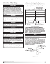
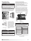
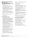
5. Set the Low Fire Time Delay
Set the low fire time delay to 75% of its maximum
setting. See below for location of the time delay setting.
6. Set the Maximum Firing Rate
Monitor the unit’s actual temperature rise by placing
a thermocouple in the unit’s inlet and a second in the
discharge, three duct diameters downstream of the
burner.
Send the unit to maximum fire by disconnecting and
isolating the proper wire on the Maxitrol 14 amplifier.
While monitoring the units temperature rise, set the
maximum firing rate by adjusting the separate regulator
or combined regulator (shown on page 13) until the
designed temperature rise is achieved. After setting the
maximum firing rate, reconnect the wire to the amplifier.
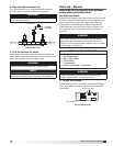
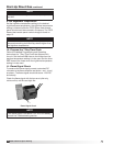
Start-Up Direct Gas
• 50/50 Recirculation
The proper static pressure
should be between 0.5 and
0.8 inches wc. On units with
motors 15 hp and less, adjust
the fan rpm by means of the
adjustable drive pulley. For
units with motors greater
than 15 hp, the drive pulley is
fixed. To change the fan rpm,
a new pulley will have to be
acquired.
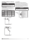
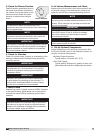
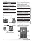
4b. Set the Burner Air Pressure Differential
With the fan running and discharging 70°F air, connect
a U-Tube manometer to the outer sensing probes (see
below) and measure the static pressure across the
burner.
IMPORTANT
Proper air velocity over the burner is critical on direct
fired gas units. If the air velocity is not within the unit
specifications, the unit will not operate efficiently, may
have sporadic shutdowns and may produce excessive
carbon monoxide (CO) or other gases.
NOTE
When required pressure is obtained, be sure to
reconnect the outer sensing probes.
NOTE
To increase the static pressure, increase the fan rpm.
To decrease the static pressure, decrease the fan
rpm.
Top Baffle
Airflow
Burner
Bottom Baffle
Burner and Baffles
0.5 - 0.8 in. WC
8
7
6
5
Outer Sensing Probes
Measuring the Pressure Drop
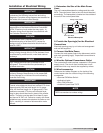
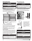
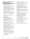
Direct Gas Nameplate
“ W.C.
“ W.C.
“ W.C.
F
PSI
“ W.C.
“ W.C.
MAX BTU/HR
BTU/H MAX
NORMAL MANIFOLD
PRESSURE
PRESSION D’ADMISSION
NORMALE
MIN GAS
PRESSURE
PRESSION DE GAZ
MIN BURNER
PRESSURE DROP
PERTE MIN DE PRESSION
DANS LE BRULEUR
TYPE OF GAS
NATURE DU GAZ
MIN BTU/HR
BTU/H MIN
MIN GAS PRESSURE
FOR MAX OUTPUT
PRESSION DE GAZ MIN
POUR PUISSANCE MAX
MAX BURNER
PRESSURE DROP
PERTE MAX DE PRESSION
DANS LE BRULEUR
MAX GAS
PRESSURE
PRESSION DE GAZ
MAX
DESIGN ∆T
∆T NORMALE
EQUIPPED FOR
CONCU POUR
SCFM
“ W.C.
EXTERNAL STATIC PRESSURE
PRESSION STATIQUE EXTERIEURE
AGAINST
CONTE
NOTE
Do not set the burner maximum firing rate based on gas
pressure. It should be set based on the unit’s designed
temperature rise shown on the direct gas label.
Set the discharge temperature: Typical 140°F
Minimum Maximum
Typical: 90°F Typical: 140°F
Maxitrol Series 14
Remove the wire from the #3 terminal
to send the unit to maximum fire
Low fire
setting (LFST)
dipswitch
®