


11
DGX Industrial Space Heating
Start-Up Direct Gas
IMPORTANT
For proper unit function and safety, follow the start-up
procedure in the exact order that it is presented.
IMPORTANT
This start-up should begin after all of the installation
procedures and the blower start-up have been
completed.
1. Check the Supply Gas Pressure
Check the supply gas pressure and compare it with
the unit’s nameplate pressure requirements. Adjust
the supply regulator as needed until the supply gas
pressure is within the specified range.
2. Check the Pilot Gas Pressure
Check the pilot gas pressure. The recommended gas
pressure is 3 inches wc. Adjust the pilot regulator as
needed. See the Gas Train Layout in the Reference
section for the location of the pilot pressure test port
and pilot regulator.
3. Check the Optional High and Low Gas
Pressure Switches
Check the settings on the high and low gas pressure
switches. The high pressure setting is typically 8inches
wc and the low pressure is setting is typically 3 inches
wc. The switches are set at the factory and should not
need adjustment. Adjust the setting if needed. See the
Gas Train Layout diagram in the Reference section for
the high and low pressure switch location.
NOTE
The purpose of the high and low gas pressure
switches is to automatically shutdown the burner
if the inlet gas pressure is too low for the burner to
safely light, or if the manifold pressure is too high for
the burner to operate safely.
Start-Up Direct Gas
• 100% Outside Air
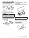
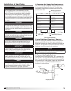
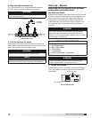
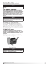
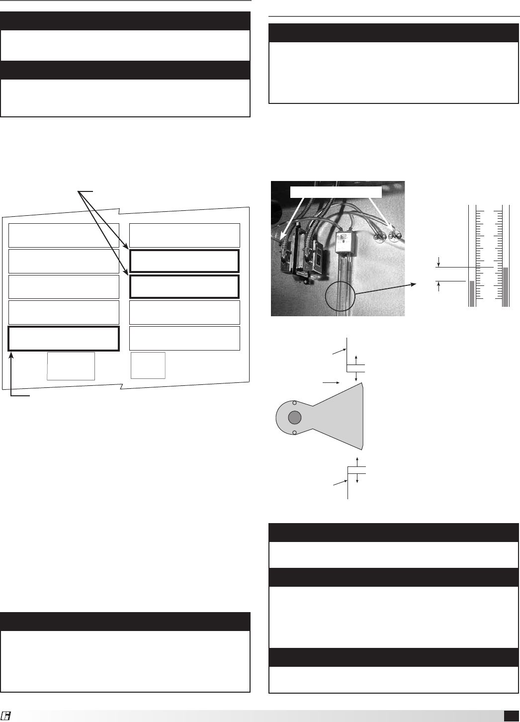
4a. Set the Burner Air Pressure Differential
With the fan running and discharging 70°F (21°C) air,
connect a U-Tube manometer to the outer sensing probes
(see below) and measure the static pressure across the
burner.
The proper static pressure
should be between 0.625
and 0.675 inches wc. If
needed, evenly adjust the
baffles above and below the
burner, keeping the burner
centered in the opening
until the required pressure is
obtained.
Adjustable
Top Baffle
Airflow
Burner
Adjustable
Bottom Baffle
Burner and Baffles
9
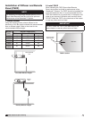
8
7
6
0.625 - 0.675 in. WC
Outer Sensing Probes
Measuring the Pressure Drop
IMPORTANT
Proper air velocity over the burner is critical on direct
fired gas units. If the air velocity is not within the unit
specifications, the unit will not operate efficiently, may
have sporadic shutdowns and may produce excessive
carbon monoxide (CO) or other gases.
NOTE
When required pressure is obtained, be sure to
reconnect the outer sensing probes.
IMPORTANT
This process may need to be repeated until the proper
pressure is achieved. This adjustment will change the
air quantity delivered by the unit and therefore the air
quantity delivered should be rechecked. Refer to the
Blower Start-Up section.
NOTE
To increase the static pressure decrease the opening.
To decrease the static pressure increase the opening.
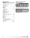
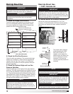
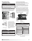
Direct Gas Nameplate
“ W.C.
“ W.C.
“ W.C.
F
PSI
“ W.C.
“ W.C.
MAX BTU/HR
BTU/H MAX
NORMAL MANIFOLD
PRESSURE
PRESSION DÕADMISSION
NORMALE
MIN GAS
PRESSURE
PRESSION DE GAZ
MIN BURNER
PRESSURE DROP
PERTE MIN DE PRESSION
DANS LE BRULEUR
TYPE OF GAS
NATURE DU GAZ
MIN BTU/HR
BTU/H MIN
MIN GAS PRESSURE
FOR MAX OUTPUT
PRESSION DE GAZ MIN
POUR PUISSANCE MAX
MAX BURNER
PRESSURE DROP
PERTE MAX DE PRESSION
DANS LE BRULEUR
MAX GAS
PRESSURE
PRESSION DE GAZ
MAX
DESIGN ∆T
∆T NORMALE
EQUIPPED FOR
CONCU POUR
SCFM
“ W.C.
EXTERNAL STATIC PRESSURE
PRESSION STATIQUE EXTERIEURE
AGAINST
CONTE
Minimum and maximum gas
pressures for maximum output
Type of gas
Start-Up Direct Gas
®