


6 684025
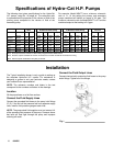
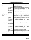
Specifications of Hydra–Cat H.P. Pumps
The followin
g
chart
g
ives specifications for the Hydra-Cat
H.P. pumps, usin
g
No. 10 wei
g
ht oil. The volumetric ratio
is expressed as the proportion of the volume of fluid of the
primary pump compared to the volume of fluid of the
secondary pump.
For example, Model 965477 has a minimum volumetric
ratio of 1:1. At this settin
g
the primary and secondary
pumps combined will deliver an output of 3.0
g
pm. The
maximum volumetric ratio for Model 965477 is 3:1 and the
combined output at that setting is 2.0 gpm.
Ratio At Minimum Ratio Settin
g
At Maximum Ratio Settin
g
Lower ID
Air Motor Assembl
y
Min Max Stall Stall
O
utput
O
utput Stall Stall
O
utput
O
utput Master Slave
Part No. PSI Bar GPM LPM PSI Bar GPM LPM DF DF
Premier
965
4
8
11.
50
4.
50
5333
368
3
.
8
14.4 727
3
50
22.
8
1
0
.
6
9
6
Premier
965
47
9
2.
00
6
.
00
4444
30
74.
6
17.
3
5
714
39
4
3
.
6
1
3
.4 12
6
Kin
g
965
477 1.
00
3
.
00
3803
2
6
2
3
.
0
11.
5
5
7
0
4
393
2.
0
7.7
6
6
Kin
g
965
47
8
1.
50
4.
50
30
42 21
0
3
.
8
14.4 414
8
2
86
2.
8
1
0
.
6
9
6
Kin
g
965
4
66
3
.
00
9
.
00
1
90
11
3
1
6
.1 2
3
.
0
22
8
21
5
7
5
.1 1
9
.2 1
8
6
Note: All Output Pressures Limited To 5000 PSI By Integral Pressure Relief Valves
Note: Pressure outputs calculated at 100 PSI Air Pressure for Premier and 90 PSI Air Pressure for King
Note: Volume outputs calculated at 40 cycles per minute.
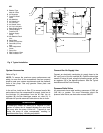
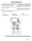
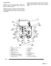
Installation
The Typical Installation shown is only a
g
uide to settin
g
up
the complete Hydra-Cat H.P. system. For assistance in
desi
g
nin
g
a system to suit your particular needs, contact
your nearest Graco representative.
NOTE: The reference numbers and letters in the text
correspond to the numbers and letters in the drawings.
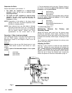
Location
Sit the proportioner on a flat floor surface.
Connect the Fluid Supply Lines
Connect the
g
rounded fluid hoses to the pump inlet fittin
g
s
(P, R). If the unit will be pressure fed from separate supply
units, install a fluid pressure gauge at each inlet.
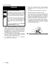
NOTE: The pressurized fluid supplies must not exceed 1/4
of the operatin
g
fluid pressure of the pump. Pressure above
that level will feed ri
g
ht throu
g
h the pump and improper
rationing will result.
Connect the Fluid Output Lines
Connect electronically conductive fluid hoses to the pump
outlet fittings. Tighten all of the fittings.
Fig. 1