


12 684025
Checking the Ratio
Note: The mix ratio must be checked at the normal
operatin
g
fluid pressure of the pump. Most mixer
manifolds provide a means for checkin
g
mix ratio
that includes needle valves for adjustin
g
the fluid
pressure during the test. The following procedure is
an example of how to properly check the mix ratio.
1. Open the mixer manifold and trigger your spray gun.
2. Set your operatin
g
pressure. After determinin
g
the
operatin
g
pressure, release the spray
g
un tri
gg
er and
engage the safety latch.
3. Close the mixer manifold inlet valves.
4. Sli
g
htly open the samplin
g
valve on the secondary
pump side. Sli
g
htly open the samplin
g
valve on the
primary pump side. This will prevent pressure from
buildin
g
up on the secondary pump, causin
g
the relief
valve to open.
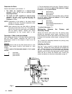
5. Place a
g
rounded waste container under the samplin
g
valve.
6. Open the mixer manifold. Use the sampling valves to
adjust the pressures to your
normal operatin
g
pressures.
7. Close the mixer manifold. Put the samplin
g
containers under the sampling valves.
8. Open the mixer manifold. Check the ratio; make sure
the pressure is within 20% of your normal operatin
g
pressure. Close the mixer manifold when enou
g
h
fluid has been dispensed into the samplin
g
containers.
NOTE: If the pressure readings are not within 20% of
your normal operatin
g
pressure, follow the
flushin
g
procedure on pa
g
e 11, then take a
sample a
g
ain. If your sample ratio is incorrect,
there is a problem with the sampling valves, ratio
settin
g
, or pump operation. Check the ratio
setting or service the sampling valves or pump.
Maintenance
Pump Lubrication
Wet Cups
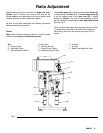
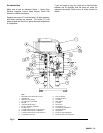
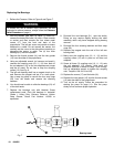
Each of the fluid cylinders has a wet cup (18) at the top
that must be kept lubricated. See figure 6. The wet cups
should be inspected and filled on a weekly basis, or
more frequently if found to be dry. To inspect the wet
cups, follow the pressure relief procedure on page 11.
Bearings
Many of the bearin
g
surfaces on the proportioner are
permanently lubricated or are self lubricating. There are
four main bearings (21) on the lever arm
that must be
lubricated
on a regular interval. The lubrication interval
is every six months in single shift operation. To lubricate
the bearin
g
s, follow the pressure relief procedure on
page 11.
WARNING WARNING
To reduce the risk of serious injury whenever you are
instructed to relieve pressure, always follow the Pressure
Relief Procedure on page 11.
To reduce the risk of serious injury whenever you are
instructed to relieve pressure, always follow the Pressure
Relief Procedure on page 11.
With the bleeder type main air valve (1) turned off,
remove the thumb screws (14) and the two guards (15)
from the sides of the proportioner. The wet cups (18)
should be filled to 1/3 full with Graco Throat Seal Liquid
(TSL) or compatible solvent.
The packing nuts (19) are torqued at the factory and are
ready for operation. If one becomes loose and there is
leaking from the throat packings, relieve the pressure,
then torque the nut to 136–149 N.m (100–110 ft-lb)
usin
g
the supplied wrench (20). Do this whenever
necessary. Do not over tighten the packing nut.
With the bleeder type main air valve turned off, remove
the twenty hex bolts (16) with a 13mm wrench or socket
and then remove the four sheet metal covers (17) from
the front and back of the proportioner.
The left rear cover may contain a sensor attached to a
cable. Do not remove the sensor, but carefully set the
cover to the side without strainin
g
or dama
g
in
g
the
sensor or cable. The four main bearin
g
s (21) are now
exposed. Use the adapter (205532) provided to grease all
four bearin
g
s. One or two squirts (2-3 cc) will be
sufficient.