


684025 11
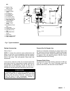
Operation
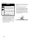
WARNING
System Flushing
INJECTION HAZARD
The system pressure must be manually
relieved to prevent the system from starting or
sprayin
g
accidentally. Fluid under hi
g
h
pressure can be injected through the skin and
cause serious injury. To reduce the risk of an
injury from injection. To reduce the risk of
parts, follow the Pressure Relief Procedure
whenever you:
• are instructed to relieve the pressure,
• stop spraying,
• check or service any of the system
equipment,
• or install or clean the spray tips.
The pumps were tested with li
g
htwei
g
ht oil at the factory.
Before operating the pump, thoroughly flush the Hydra-Cat
H.P. to prevent contamination of your fluids.
NOTE:
Flush the mixer, hose and
g
un often enou
g
h to prevent
fluid from reactin
g
or curin
g
in them. Contact
your fluid
manufacturer for the effective pot life of the fluid you are
using.
1. Put the pump intake hoses into a 5
g
allon (20 liter)
container of a compatible solvent. Refer to the fluid
manufacturer’s recommendations.
2. Start the pump as explained below.
3. Do not install a spray tip yet. Hold a metal part of the
g
un firmly to the side of a
g
rounded metal pail. Usin
g
the lowest possible air pressure to the air motor that
will activate the pump, trigger the gun into the pail.
Pressure Relief Procedure
1. Lock the spray gun’s trigger safety.
2. Shut off ALL fluid supplies to the pump.
3. Close the bleed-type master air valve.
4. Unlock the spray gun’s trigger safety.
5. Hold a metal part of the spray gun firmly to the side
of a grounded metal pail. Trigger the spray gun into
the pail to relieve pressure.
6. Lock the spray gun’s trigger safety.
7. Open the sampling valves, having a container ready
to catch the drainage.
8. If you suspect that the spray tip or nozzle or the
hose is completely clogged or that pressure has not
been fully relieved after followin
g
the steps above,
follow this procedure: Very slowly loosen the tip
guard retaining nut or hose end coupling and relieve
pressure
g
radually, then loosen completely. Now
clear the obstruction.
4. When clean solvent comes from the spray
g
un,
release the trigger and carefully check all connections
in the system for leaks.
5. Take the hoses out of the solvent, and trigger the gun
until all the solvent has been pumped out of the hoses.
Immediately turn off the bleeder-type master air valve.
Start the Pump
1. Close the bleed-type master air valve, and turn the air
regulator knob all the way out (counterclockwise).
2. Turn on the main air supply.
3. With the mixer manifold handle in the open position,
tri
gg
er the
g
un, slowly open the bleed-type master air
valve, and turn the air re
g
ulator knob clockwise until
the pump starts.
4. Allow the pump to cycle slowly until all the air is pushed
out of the lines. Release the trigger. The pump will stall
against the pressure.
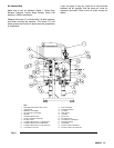
5. The manifold handle controls fluid flow. With the lever
of the manifold in the open (down) position, base and
catalyst are supplied to the
g
un. To stop the flow,
move the handle to the closed (up) position.
Standard Operating Flushing
Use the solvent valves to flush contaminants and mixed
fluids from the mixer manifold, hose and spray gun. Follow
the procedure provided with the mix manifold assembly.