


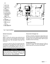

684025 17
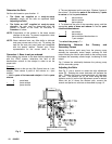
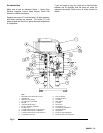
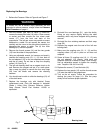
Reconnecting the Displacement Pump
CAUTION
1. Make sure the couplin
g
nut (10,11) and the couplin
g
collars (12) are in place on the displacement rod. See
Fig. 6.
Be sure to use an overhead hoist when lifting, moving or
disconnectin
g
the air motor. This air motor wei
g
hs 145
lbs. and is too heavy for one person to handle. A lift ring
is provided on the motor for this purpose.
2. Use at least two people to hold the displacement pump
while another reconnects it to the frame (see the
CAUTION in the removal procedure above).
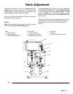
3. Position and orient the displacement pump (3,4) to the
frame (5) as was noted in step 6 under Disconnectin
g
the Displacement Pump.
4. Position the displacement pump (3,4) on the tie rods
(7).
5. Screw the nuts (8) onto the tie rods (7) and torque to
81–89 N.m (60–66 ft-lb).
6. Screw the couplin
g
nut (10) onto the rod adapter (13)
loosely. Hold the rod adapter flats with a wrench to
keep it from turnin
g
. Use an adjustable wrench to
tighten the coupling nut. Torque to 196–210 N.m ft-lb).
7. Fill the wet cup (18) 1/3 full with Graco Throat Seal
Lubricant or compatible solvent.
8. Reconnect all hoses.
9. Replace the two
g
uards (15) and the thumb screws
(14) from the sides of the proportioner.
10. Turn on the air supply. Follow the procedure for
startin
g
the pump on pa
g
e 11. Run the pump slowly at
first to ensure proper operation.
5. Note the relative position of the air motor’s air
connection to the frame. The air motor must be
returned to its original orientation.
6. Usin
g
an adjustable wrench (or hammer and punch),
unscrew the couplin
g
nut (9) from the rod adapter
(13). Do not lose or drop the coupling collars (12). See
Fig. 6.
7. Hold the tie rod flats with a wrench to keep the rods
from turnin
g
. Unscrew the nuts (8) from the tie rods
(6). Carefully remove the air motor (2) from the frame.
8. Refer to the separate manual supplied for air motor
service. Be sure to look at the model number stamped
on the air motor and use the appropriate manual for
service and reference.
Reconnecting the Air Motor
1. If the connectin
g
rod has been removed from the Air
Motor Stud as a part of servicin
g
, be sure to use
thread adhesive when reinstallin
g
the connectin
g
rod
on to the Air Motor Stud.
2. Make sure the couplin
g
nut (9) and the couplin
g
collars (12) are in place on the rod adapter (13).
WARNING
To reduce the risk of serious injury whenever you are
instructed to relieve pressure, always follow the Pressure
Relief Procedure on page 11.
3. Use an overhead hoist to position the air motor on the
frame in the same orientation as noted in step 5 of
disconnecting the air motor. (see the CAUTION in the
removal procedure above).
11. Before returnin
g
the pump to production, relieve the
pressure and re-torque the packing nut (2) to 136–
149 N.m (100–110 ft-lb). The must be performed
after the pump has been cycled a number of times
4. Position the air motor (2) on the tie rods (6).
5. Screw the nuts (8) onto the tie rods (6) and torque to
81–89 N.m (60–66 ft-lb).
Disconnecting the Air Motor
1. Relieve the pressure.
6. Screw the couplin
g
nut (9) onto the rod adapter (13)
loosely. Hold the rod adapter flats with a wrench to
keep it from turnin
g
. Use an adjustable wrench to
tighten the coupling nut. Torque to 196–210 N.m ft-lb).
WARNING
7. Reconnect the air hose
To reduce the risk of serious injury whenever you are
instructed to relieve pressure, always follow the Pressure
Relief Procedure on page 11.
8. Replace the two
g
uards (15) and the thumb screws
(14) onto the sides of the proportioner.
2. With the bleeder type main air valve turned off,
disconnect the air hose from the air motor.
3. Remove the thumb screws (14) and the two
g
uards
(15) from the sides of the proportioner.
4. Disconnect the air motor (2) from the frame (5) as
follows:
9. Turn on the air supply. Follow the procedure for startin
g
the pump on pa
g
e 11. Run the pump slowly at first to
ensure proper operation