


14 684025
Troubleshooting
Troubleshooting Techniques
Because the pumps are mechanically linked, the action of
one pump can affect the readin
g
s of the second pump.
Therefore, the key to successful troubleshooting is to be
sure to isolate the problem.
For example, if the secondary pump pressure, as read on
the
g
au
g
e, is low and slu
gg
ish durin
g
the pump
chan
g
eover. The most likely problem is a bindin
g
primary
pump. To isolate the problem:
1. Relieve the pressure.
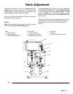
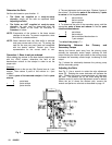
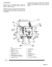
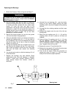
2. With the sampling valves still open, set the air supply
regulator to the lowest setting and open the bleed-
type main air valve (1). Refer to fi
g
ure 6. Increase
the re
g
ulator settin
g
until the pump just be
g
ins to
move. Notice the position of the secondary pump
(11). Turn off the bleeder-type main air valve (1) so
that the secondary pump rod is at its lowest position
when the pump stops.
8. With the main bleed-type air valve (1) off, remove
the thumb screws (14) and
g
uards (15) from each
side of the proportioner.
9. Unscrew the connectin
g
rod nut (10) from the
primary pump. Now you can verify the operation of
the secondary pump alone.
Reinstall the
g
uards (15) on both sides of the
proportioner. Turn the main air valve (1) back on
and carefully increase the air pressure.
10. Using the sampling valves at the mixer manifold:
A. Open and close the samplin
g
valves and check
for pump stallin
g
on both the up and down
strokes.
B. Check for rapid
g
au
g
e response durin
g
the
pump changeover
11. When the operation of the secondary side has been
verified, reconnect the connectin
g
rod (10) of the
primary pump.
WARNING WARNING
To reduce the risk of a serious injury, always follow the
Pressure Relief Procedure on page 11 whenever you
are instructed to relieve the pressure.
Use very low air pressure to the air motor when
troubleshootin
g
the system. This system can produce
very high fluid pressure, which can cause serious injury,
3. With the main bleed-type air valve (1) off, remove
the thumb screws (14) and
g
uards (15) from each
side of the proportioner.
4. Unscrew the connectin
g
rod nut (11) from the
secondary pump. Now you can verify the operation
of the primary pump alone.
includin
g
injection, splashin
g
in the eyes or on the skin,
and injury from moving parts.
To reduce the risk of a serious injury, always follow the
Pressure Relief Procedure on page 11 if the problem
you are checking does not require air.
Reinstall the
g
uards (15) on both sides of the
proportioner. Turn the main air valve (1) back on
and carefully increase the air pressure.
5. Using the sampling valves at the mixer manifold:
WARNING
A. Open and close the samplin
g
valves and check
for pump stallin
g
on both the up and down
strokes.
B. Check for rapid
g
au
g
e response durin
g
the
pump changeover
To reduce the risk of injurin
g
or amputatin
g
your hands,
fin
g
ers, or other body parts, never place your hands,
body or tools inside the safety panels for any reason
while the unit is operating.
6. When the operation of the primary side has been
verified, reconnect the connectin
g
rod (11) of the
secondary.
7. With the sampling valves still open, set the air supply
regulator to the lowest setting and open the bleed-
type main air valve (1). Increase the regulator setting
until the pump just be
g
ins to move. Notice the
position of the primary pump. Turn off the bleeder-
type main air valve (1) so that the primary pump rod
(10) is at its lowest position when the pump stops.