


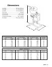

18 684025
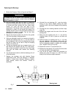
Replacing the Bearings
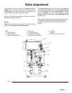
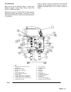
1. Relieve the Pressure. Refer to Figure 6 and Figure 7.
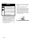
WARNING
To reduce the risk of serious injury whenever you are
instructed to relieve pressure, always follow the Pressure
Relief Procedure on page 11.
2. With the bleeder type main air valve (1) turned off,
remove the twenty hex bolts (16) with a 13mm wrench
or socket and then remove the four sheet metal
covers (17) from the front and back of the
proportioner. The left rear cover may contain a sensor
attached to a cable. Do not remove the sensor, but
carefully set the cover to the side without strainin
g
or
dama
g
in
g
the sensor or cable. The (4) four main
bearings (21) are now exposed.
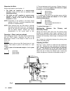
3. Remove the thumb screws (14) and the two
g
uards
(15) from the sides of the proportioner.
4. Usin
g
an adjustable wrench (or hammer and punch),
unscrew the couplin
g
nuts (10, 11, 12) from each of
the rod adapters (13) on the two displacement pumps
and the air motor. Do not lose or drop the couplin
g
collars (12). See Fig. 6.
5. The left rear bearin
g
shaft has a ma
g
net stuck on its
end. Remove the ma
g
net and put it in a safe place.
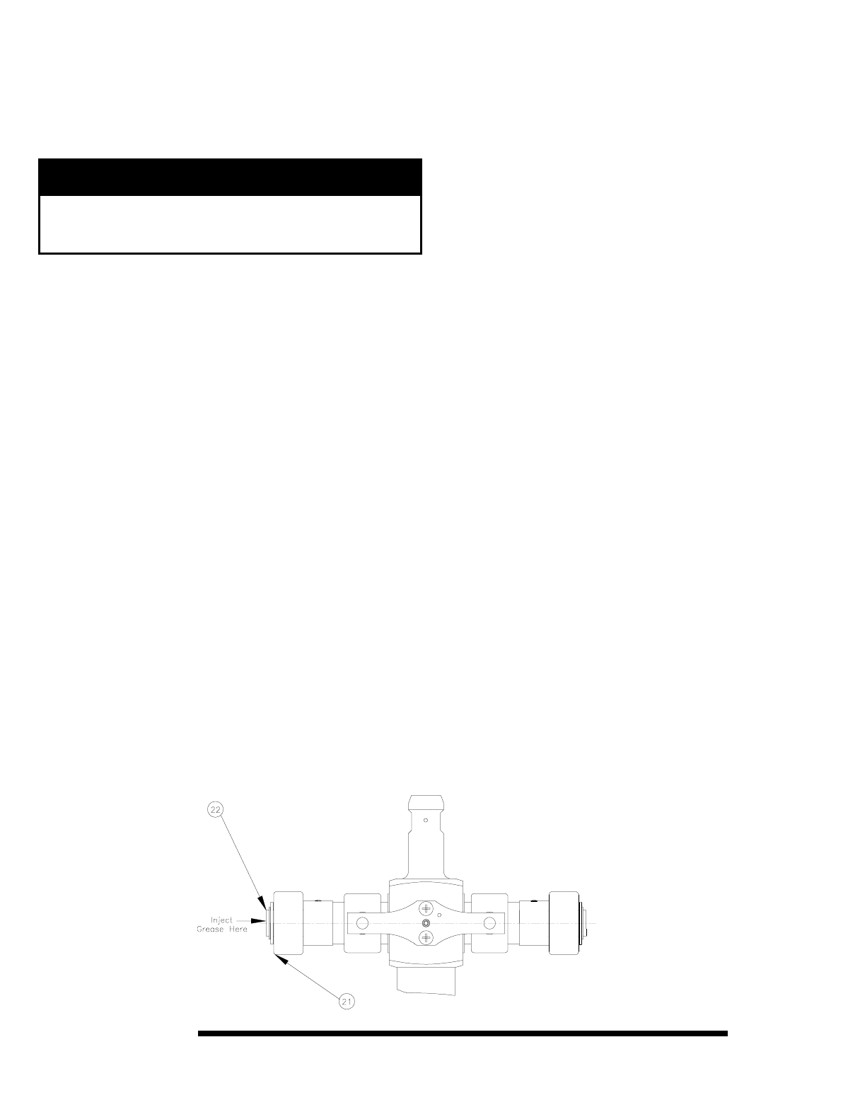
Use a snap rin
g
pliers to remove the four snap rin
g
s
(22) from the shafts and remove the retainin
g
washers.
6. You should now be able to slide the bearin
g
s (21) off
of the shaft ends.
7. Replace the bearin
g
s only with identical Graco
replacement parts. Pack the bearin
g
s in Industrial
Grade 1, Heavy Duty, Extreme Pressure, Lithium
Soap Grease, Graco Part Number 110293 or
equivalent.
8. Re-install the new bearin
g
s (21) onto the shafts.
Doin
g
so may require sli
g
htly shiftin
g
the shaft
assembly which may have dropped durin
g
bearin
g
removal.
9. Re-install the four retainin
g
washers and their snap
rings (22).
10. Replace the ma
g
net onto the end of the left rear
bearing shaft.
11. Make sure the couplin
g
nuts (10, 11, 12) and the
couplin
g
collars (12) are in place on all three rod
adapters.
12. Screw all three (3) couplin
g
nuts (10, 11, 12) onto
the rod adapters (13) loosely. Hold each rod
adapters flats with a wrench to keep it from turnin
g
.
Use an adjustable wrench to ti
g
hten the couplin
g
nuts. Torque to 196–210 N.m ft-lb).
13. Replace the covers (17) and the bolts (16).
14. Replace the two
g
uards (15) and the thumb screws
(14) onto the sides of the proportioner.
15. Turn on the air supply. Follow the procedure for
startin
g
the pump on pa
g
e (11). Run the pump
slowly at first to ensure proper operation.
Bearing Inset
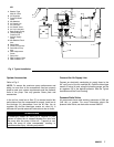
Fig. 7