


8 308550
Installation
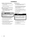
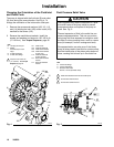
Installation of Remote Pilot Air Lines
1. Refer to Parts Drawings. Connect air line to pump
as in preceding steps.
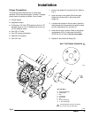
2. Connect 1/4 in. O.D. tubing to push type connec-
tors (14) on air motor of pump.
NOTE: by replacing the push type connectors, other
sizes or types of fittings may be used. The new fittings
will require 1/8 in. npt threads.
3. Connect remaining ends of tubes to external air
signal, such as Graco’s Cycleflo (P/N 195264) or
Cycleflo II (P/N195265) controllers.
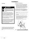
Mountings
CAUTION
The pump exhaust air may contain contaminants.
Ventilate to a remote area if the contaminants
could affect your fluid supply. See Air Exhaust
Ventilation on page 11.
D Be sure the mounting surface can support the
weight of the pump, hoses, and accessories, as
well as the stress caused during operation.
D For all mountings, be sure the pump is bolted
directly to the mounting surface.
D For ease of operation and service, mount the pump
so the air valve cover (2), air inlet, and fluid inlet
and outlet ports are easily accessible.
D Rubber Foot Mounting Kit 236452 is available to
reduce noise and vibration during operation.
Fluid Suction Line
1. The pump fluid inlet (R) is a 2” raised face flange.
Refer to Flange Connections on page 9.
2. If the fluid inlet pressure to the pump is more than
25% of the outlet working pressure, the ball check
valves will not close fast enough, resulting in
inefficient pump operation.
3. At inlet fluid pressures greater than 15 psi
(0.1 MPa, 1 bar), diaphragm life will be shortened.
4. See the Technical Data on page 34 for maximum
suction lift (wet and dry).
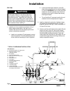
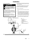
Fluid Outlet Line
WARNING
A fluid drain valve (J) is required to relieve pres-
sure in the hose if it is plugged. The drain valve
reduces the risk of serious injury, including splash-
ing in the eyes or on the skin, or contamination
from hazardous fluids when relieving pressure.
Install the valve close to the pump fluid outlet. See
Fig. 2.
1. The pump fluid outlet (S) is a 2” raised face flange.
Refer to Flange Connections on page 9.
2. Install a fluid drain valve (J) near the fluid outlet.
See the WARNING above.
3. Install a shutoff valve (K) in the fluid outlet line.