


308550 7
Installation
Air Line
WARNING
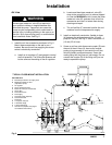
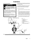
A bleed-type master air valve (B) is required in
your system to relieve air trapped between this
valve and the pump. Trapped air can cause the
pump to cycle unexpectedly, which could result in
serious injury, including splashing in the eyes or on
the skin, injury from moving parts, or contamination
from hazardous fluids. See Fig. 2.
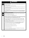
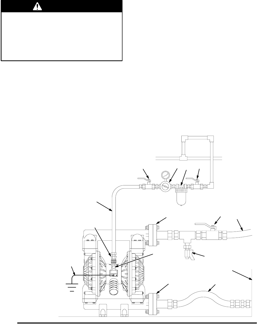
1. Install the air line accessories as shown in Fig. 2.
Mount these accessories on the wall or on a
bracket. Be sure the air line supplying the acces-
sories is electrically conductive.
a. Install an air regulator (C) and gauge to control
the fluid pressure. The fluid outlet pressure will
be the same as the setting of the air regulator.
b. Locate one bleed-type master air valve (B)
close to the pump and use it to relieve trapped
air. See the WARNING at left. Locate the other
master air valve (E) upstream from all air line
accessories and use it to isolate them during
cleaning and repair.
c. The air line filter (F) removes harmful dirt and
moisture from the compressed air supply.
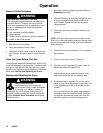
2. Install an electrically conductive, flexible air hose
(A) between the accessories and the 1/2 npt(f)
pump air inlet (N). See Fig. 2. Use a minimum 1/2”
(13 mm) ID air hose.
3. Screw an air line quick disconnect coupler (D) onto
the end of the air hose (A); be sure the coupler
porting is large enough to not restrict the air flow,
which will affect pump performance. Screw the
mating fitting into the pump air inlet snugly. Do not
connect the coupler (D) to the fitting until you are
ready to operate the pump.
04614B
KEY FOR FIG. 2
A Electrically conductive air supply hose
B Bleed-type master air valve
(required for pump)
C Air regulator
D Air line quick disconnect
E Master air valve (for accessories)
F Air line filter
G Fluid suction hose
H Fluid supply
J Fluid drain valve (required)
K Fluid shutoff valve
l Fluid hose
N 1/2 npt(f) air inlet port
R 2” fluid inlet flange
S 2” fluid outlet flange
Y Ground wire (required; see page 6
for installation instructions)
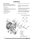
Fig. 2
TYPICAL FLOOR-MOUNT INSTALLATION
Y
J
F
BEC
A
D
K
L
G
H
R
S
N