


18 308550
Service
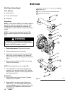
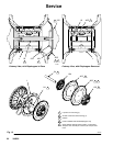
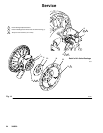
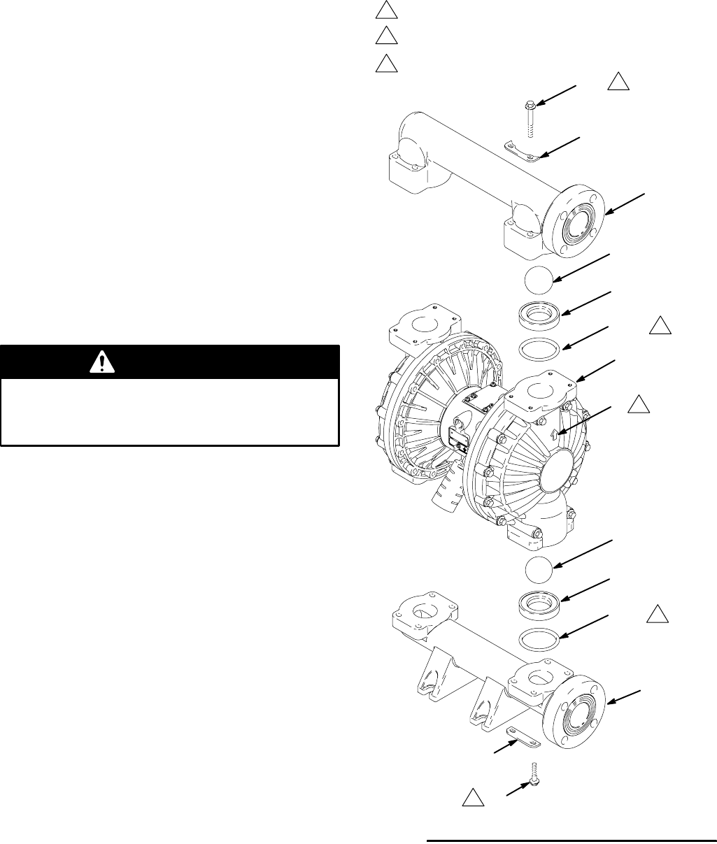
Ball Check Valve Repair
Tools Required
D Torque wrench
D 10 mm socket wrench
D O-ring pick
Disassembly
NOTE: A Fluid Section Repair Kit is available. Refer to
page 27 to order the correct kit for your pump. Parts
included in the kit are marked with an asterisk, for
example (201*). Use all the parts in the kit for the best
results.
NOTE: To ensure proper seating of the balls (301),
always replace the seats (201) when replacing the
balls.
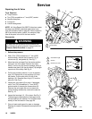
WARNING
To reduce the risk of serious injury whenever you
are instructed to relieve pressure, always follow the
Pressure Relief Procedure on page 12.
1. Relieve the pressure. Disconnect all hoses.
2. Remove the pump from its mounting.
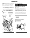
3. Using a 10 mm socket wrench, remove the eight
bolts (106), and four washers (113), holding the
outlet manifold (103) to the fluid covers (101). See
Fig. 11.
4. Remove the seats (201), balls (301), and o-rings
(202) from the manifold.
NOTE: Some models do not use o-rings (202).
5. Turn the pump over and remove the bolts (112),
washers (114), and inlet manifold (102). Remove
the seats (201), balls (301), and o-rings (202) from
the fluid covers (101).
Reassembly
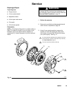
1. Clean all parts and inspect for wear or damage.
Replace parts as needed.
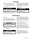
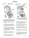
2. Reassemble in the reverse order, following all
notes in Fig. 11. Be sure the ball checks are as-
sembled exactly as shown. The arrows (A) on the
fluid covers (101) must point toward the outlet
manifold (103).
Fig. 11
1
2
Torque to 150–160 in–lb (17–18 NSm). See Torque Se-
quence, page 32.
Arrow (A) must point toward outlet manifold (103).
106
103
101
A
201*
301*
112
102
201*
301*
2
1
1
202*
202*
3
Not used on some models.
3
3
04619C
113
114