


20 308550
Service
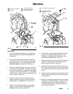
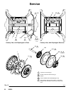
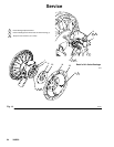
4. Unscrew one outer plate (105) from the diaphragm
shaft (24). Remove one diaphragm (401), and the
inner plate (104). See Fig. 13.
For overmolded diaphragms: Grip both dia-
phragms securely around the outer edge and
rotate counterclockwise. One diaphragm assembly
will come free and the other will remain attached to
the shaft. Remove the freed diaphragm and air
side plate.
NOTE: PTFE models include a PTFE diaphragm (403)
in addition to the backup diaphragm (401).
5. Pull the other diaphragm assembly and the dia-
phragm shaft (24) out of the center housing (1).
Hold the shaft flats with a 19 mm open–end
wrench, and remove the outer plate (105) from the
shaft. Disassemble the remaining diaphragm
assembly.
For overmolded diaphragms: Pull the other dia-
phragm assembly and the diaphragm shaft (24)
out of the center housing (1). Hold the shaft flats
with a 19 mm open–end wrench and remove the
diaphragm and air side plate from the shaft.
6. Inspect the diaphragm shaft (24) for wear or
scratches. If it is damaged, inspect the bearings
(19) in place. If the bearings are damaged, refer to
page 23.
7. Reach into the center housing (1) with an o-ring
pick and hook the u-cup packings (402), then pull
them out of the housing. This can be done with the
bearings (19) in place.
8. Clean all parts and inspect for wear or damage.
Replace parts as needed.
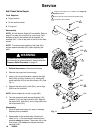
Reassembly – Standard Diaphragms
1. Grease the shaft u-cup packings (402*) and install
them so the lips face out of the housing (1). See
Fig. 13.
2. Grease the length and ends of the diaphragm shaft
(24) and slide it through the housing (1).
3. Assemble the inner diaphragm plates (104), dia-
phragms (401*), PTFE diaphragms (403*, if pres-
ent), and outer diaphragm plates (105) exactly as
shown in Fig. 13. These parts must be assembled
correctly.
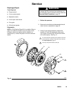
4. Apply medium-strength (blue) LoctiteR or equiva-
lent to the threads of the fluid-side plates (105).
Hold one of the outer plates (105) with a wrench,
and torque the other outer plate to 20 to 25 ft-lb
(27 to 34 NSm) at 100 rpm maximum. Do not
over-torque.
5. Align the fluid covers (101) and the center housing
(1) so the arrows (A) on the covers face the same
direction as the air valve (B). Secure the covers
with the screws (107 and 108), handtight. Install
the longer screws (108) in the top and bottom
holes of the covers. See Fig. 12.
6. First, torque the longer screws (108) oppositely
and evenly to 190–220 in-lb (21–25 NSm), using a
13 mm socket wrench. Then torque the shorter
screws (107). See Torque Sequence, page 32.
7. Reassemble the ball check valves and manifolds
as explained on page 18.