


308550 21
Reassembly – Overmolded Diaphragms
WARNING
To reduce the risk of serious injury, including
amputation, do not put your fingers or hand be-
tween the air cover and the diaphragm.
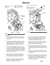
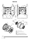
1. Lubricate and install the shaft u–cup packings
(402*) so the lips face out of the housing (1). See
Fig. 13.
2. Assemble the air side plate (104) onto the dia-
phragm (403). The wide, radiused side of the plate
must face the diaphragm. Apply medium–strength
(blue) Loctite or equivalent to the threads of the
diaphragm assembly. Screw the assembly into the
shaft (24) hand–tight.
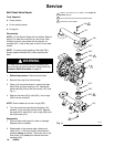
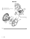
3. Grease the length and ends of the diaphragm shaft
(24). Insert the shaft/diaphragm assembly into one
side of the pump. Align the fluid cover (101) and
the center housing (1) so the arrow (A) faces the
same direction as the air valve. Secure the cover
with the screws (107 and 108), handtight.
4. Torque the longer screws (108) oppositely and
evenly to 190–220 in–lb (21–25 NSm), using a
13mm socket wrench. Then torque the shorter
screws (107). See Torque Sequence, page 32.
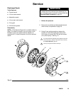
5. Assemble the other diaphragm assembly to the
shaft as explained in step 2. This diaphragm will
be lifted off the air cover at this point.
6. Supply the pump with low pressure air (less than 7
psi [0.05 MPa, 0.5 bar]). The diaphragm will very
slowly pull onto the air cover. Find the pressure
that keeps the diaphragm close enough to secure
with the screws, but does not let it contact the pilot
pin.
NOTE: Do not deform the diaphragm manually. The
diaphragm needs uniform pressure to deform properly
for maximum life.
7. Align the fluid cover (101) and the center housing
(1) so the arrow (A) faces the same direction as
the air valve. Secure the cover with two of the
longer screws (108), handtight.
NOTE: If the diaphragm contacts the pilot pin and is
forced away from the air cover, try Step 5 again. If
necessary, return to Step 3.
8. Torque the longer screws (108) oppositely and
evenly to 190–220 in–lb (21–25 NSm), using a
13mm socket wrench. Then torque the shorter
screws (107). See Torque Sequence, page 32.
9. Reassemble the ball check valves and manifolds
as explained on page 18.