


16 308550
Service
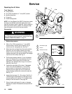
Repairing the Air Valve
Tools Required
D Torque wrench
D Torx (T20) screwdriver or 7 mm (9/32”) socket
D Needle-nose pliers
D O-ring pick
D Lithium base grease
NOTE: Air Valve Repair Kits 236273 (aluminum center
housings) and 255061 (stainless steel center hous-
ings) are available. Refer to page 28. Parts included in
the kit are marked with a symbol, for example (4{H).
Use all the parts in the kit for the best results.
Disassembly
WARNING
To reduce the risk of serious injury whenever you
are instructed to relieve pressure, always follow the
Pressure Relief Procedure on page 12.
1. Relieve the pressure.
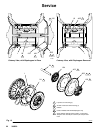
2. With a Torx (T20) screwdriver or 7 mm (9/32”)
socket wrench, remove the six screws (3), air
valve cover (2), and gasket (4). See Fig. 7.
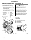
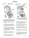
3. Move the valve carriage (5) to the center position
and pull it out of the cavity. Remove the valve
block (7) and o-ring (6) from the carriage. Using a
needle-nose pliers, pull the pilot block (18) straight
up and out of the cavity. See Fig. 8.
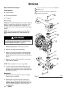
4. Pull the two actuator pistons (11) out of the bear-
ings (12). Remove the u-cup packings (10) from
the pistons. Pull the pilot pins (16) out of the
bearings (15). Remove the o-rings (17) from the
pilot pins. See Fig. 9.
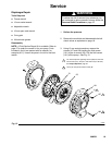
5. Inspect the valve plate (8) in place. If damaged,
use a Torx (T20) screwdriver or 7 mm (9/32”)
socket wrench to remove the three screws (3).
Remove the valve plate (8) and, on aluminum
center housing models only, remove the seal (9).
See Fig. 10.
6. Inspect the bearings (12, 15) in place. See Fig. 9.
The bearings are tapered and, if damaged, must
be removed from the outside. This requires disas-
sembly of the fluid section. See page 23.
7. Clean all parts and inspect for wear or damage.
Replace as needed. Reassemble as explained on
page 17.
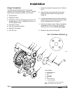
Torque to 50–60 in-lb
(5.6–6.8 NSm).
Fig. 7
3
2
4{H
2
2
04618
B
04900
H{18
5
Fig. 8
1
2
See Detail at right.
Grease.
3 Grease lower face.
1
H{7
H{6
5
2
3
3
11
16