


10 308550
Installation
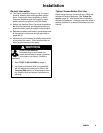
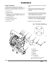
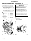
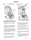
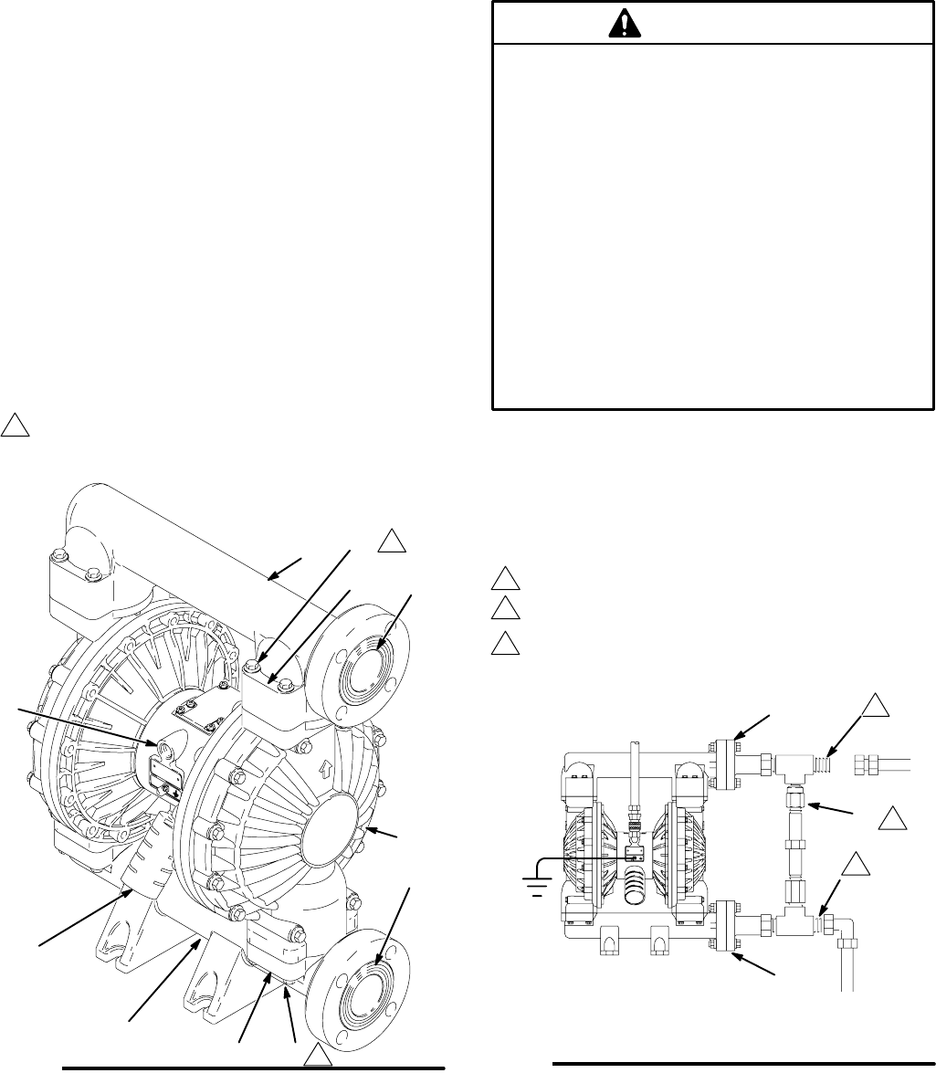
Changing the Orientation of the Fluid Inlet
and Outlet Ports
The pump is shipped with the fluid inlet (R) and outlet
(S) ports facing the same direction. See Fig. 4. To
change the orientation of the inlet and/or outlet port:
1. Remove the screws and washers (106, 112, 113
and 114) holding the inlet (102) and/or outlet (103)
manifold to the covers (101).
2. Reverse the manifold and reattach. Install the
screws and washers and torque to 150–160 in–lb
(17–18 NSm). See Torque Sequence, page 32.
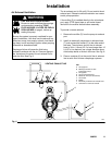
04613B
Fig. 4
1
Torque to 150–160 in–lb
(17–18 NSm). See Torque
Sequence, page 32.
KEY
N 1/2 npt(f) air inlet port
P Muffler
Air exhaust port is 3/4
npt(f) .
R 2” fluid inlet flange
S 2” fluid outlet flange
101 Fluid covers
102 Fluid inlet manifold
103 Fluid outlet manifold
106 Fluid outlet manifold
screws (top)
112 Fluid inlet manifold
screws (bottom)
113 Fluid outlet manifold
washer
114 Fluid inlet manifold
washer
N
P
R
S
1
103
102
101
1
106
112
113
114
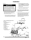
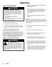
Fluid Pressure Relief Valve
Some systems may require installation of a pres-
sure relief valve at the pump outlet to prevent
overpressurization and rupture of the pump or
hose. See Fig. 5.
Thermal expansion of fluid in the outlet line can
cause overpressurization. This can occur when
using long fluid lines exposed to sunlight or ambi-
ent heat, or when pumping from a cool to a warm
area (for example, from an underground tank).
Overpressurization can also occur if the Husky
pump is being used to feed fluid to a piston pump,
and the intake valve of the piston pump does not
close, causing fluid to back up in the outlet line.
CAUTION
Fig. 5
1
2
Connect fluid inlet line here.
KEY
R 2” fluid inlet flange
S 2” fluid outlet flange
V Pressure relief valve
Part No. 112119 (stainless steel)
R
S
Connect fluid outlet line here.
1
2
3
Install valve between fluid inlet and outlet ports.
V
3
04616B