


9
C
ONDUIT
AND
FITTINGS
MUST
BE
WEATHER
‐
TIGHT
TO
PREVENT
WATER
ENTRY
INTO
THE
BUILDING
.
CAUTION
For unit protection, use a fuse or HACR circuit breaker that is
in excess of the circuit ampacity, but less than or equal to the
maximum overcurrent protection device. DO NOT EXCEED
THE MAXIMUM OVERCURRENT DEVICE SIZE SHOWN
ON UNIT DATA PLATE.
All line voltage connections must be made through weather-
proof fittings. All exterior power supply and ground wiring
must be in approved weatherproof conduit.
The main power supply wiring to the unit and low voltage
wiring to accessory controls must be done in accordance with
these instructions, the latest edition of the National Electrical
Code (ANSI/NFPA 70), and all local codes and ordinances.
All field wiring shall conform with the temperature limitations
for Type T wire (63°F/35°C rise).
The main power supply shall be three-phase, three wire. The
unit is factory wired for the voltage shown on the unit’s data
plate.
NOTE: If supply voltage is 208V, all leads on primary of trans-
former TRANS1 must be moved from the 230V to the 208V
tap.
Main power wiring should be sized for the minimum wire
ampacity shown on the unit’s database. Size wires in accor-
dance with the ampacity tables in Article 310 of the National
Electrical Code. If long wires are required, it may be neces-
sary to increase the wire size to prevent excessive voltage
drop. Wires should be sized for a maximum of 3% voltage
drop.
T
O
AVOID
PROPERTY
DAMAGE
OR
PERSONAL
INJURY
DUE
TO
FIRE
,
USE
ONLY
COPPER
CONDUCTORS
.
CAUTION
T
O
PREVEN T
IMPROPER
AND
DANGEROUS
OPERATION
DUE
TO
WIRING
ERRORS
,
LABEL
ALL
WIRES
PRIOR
TO
DISCONNECTION
WHEN
SERVICING
CONTROLS
.V
ERIFY
PROPER
OPERATION
AFTER
SERVICING
.
CAUTION
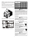
NOTE: A weather-tight disconnect switch, properly sized for
the unit total load, must be field installed. An external field
supplied disconnect may be mounted on the exterior panel.
Ensure the data plate is not covered by the field-supplied
disconnect switch.
• Some disconnect switches are not fused. Protect the
power leads at the point of distribution in accordance
with the unit data plate.
• The unit must be electrically grounded in accordance
with local codes or, in the absence of local codes,
with the latest edition of the National Electrical Code
(ANSI-NFPA 70). A ground lug is provided for this
purpose. Size grounding conductor in accordance
with Table 250-95 of the National Electrical Code. Do
not use the ground lug for connecting a neutral
conductor.
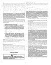
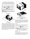
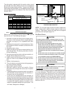
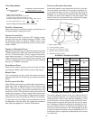
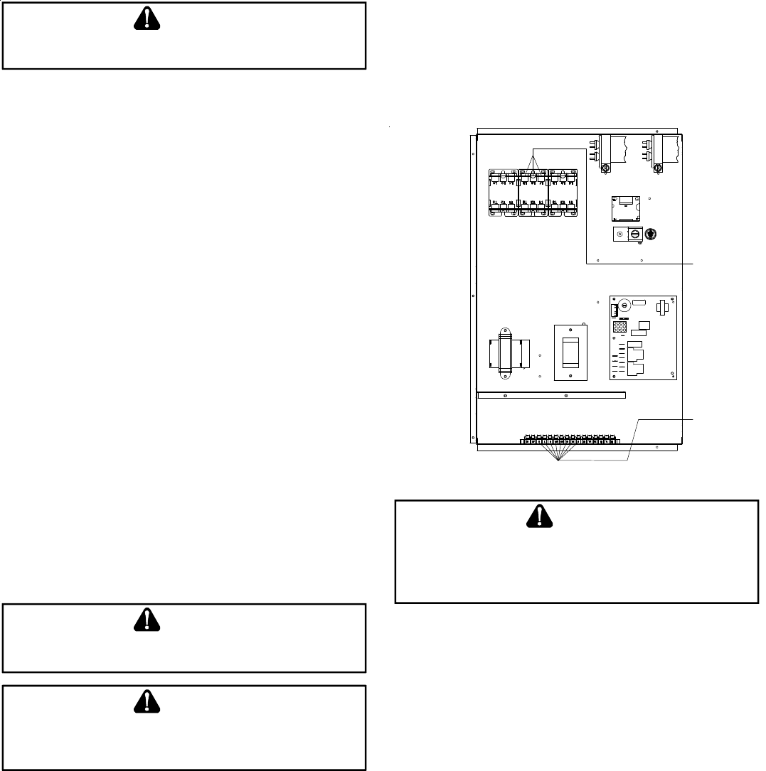
• Connect power wiring to the middle contactor within
the main control box.
3
4
2
1
6
RCCF
FAN
C
FAN
C
RCCF
FA N CFA N C
POWER
WIRING
THERMOSTAT
WIRING
POWER AND LOW VOLTAGE BLOCK LOCATIONS
F
AILURE
OF
UNIT
DUE
TO
OPERATION
ON
IMPROPER
LINE
VOLTAGE
OR
WITH
EXCESSIVE
PHASE
UNBALANCE
CONSTITUTES
PRODUCT
ABUSE
AND
WILL
VOID
YOUR
WARRANTY
AND
MAY
CAUSE
SEVERE
DAMAGE
TO
THE
UNIT
ELECT RICAL
COMPONENTS
.
WARNING
AREAS WITHOUT CONVENIENCE OUTLET
It is recommended that an independent 115V power source
be brought to the vicinity of the roof top unit for portable lights
and tools used by the service mechanic.
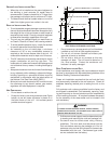
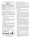
UNITS INSTALLED ON ROOF TOPS
Main power and low voltage wiring may enter the unit through
the side or through the roof curb. Install conduit connectors
at the desired entrance locations. External connectors must
be weatherproof. All holes in the unit base must be sealed
(including those around conduit nuts) to prevent water leak-
age into building. All required conduit and fittings are to be
field supplied.
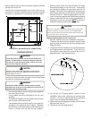
Supply voltage to roof top unit must not vary by more than
10% of the value indicated on the unit data plate. Phase
voltage unbalance must not exceed 2%. Contact your local
power company for correction of improper voltage or phase
unbalance.