


5
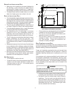
GROUND LEVEL INSTALLATIONS ONLY:
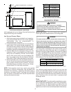
• When the unit is installed on the ground adjacent to
the building, a level concrete (or equal) base is
recommended. Prepare a base that is 3” larger than
the package unit footprint and a minimum of 3” thick.
• The base should also be located where no runoff of
water from higher ground can collect in the unit.
ROOF TOP INSTALLATIONS ONLY:
• To avoid possible property damage or personal injury,
the roof must have sufficient structural strength to carry
the weight of the unit(s) and snow or water loads as
required by local codes. Consult a structural engineer
to determine the weight capabilities of the roof.
• The unit may be installed directly on wood floors or
on Class A, Class B, or Class C roof covering material.
• To avoid possible personal injury, a safe, flat surface
for service personnel should be provided.
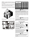
• As indicated on the unit data plate, a minimum
clearance of 36” to any combustible material is
required on the furnace access side of the unit. All
combustible materials must be kept out of this area.
• This 36” clearance must also be maintained to insure
proper combustion air and flue gas flow. The
combustion air intake and furnace flue discharge must
not be blocked for any reason, including blockage by
snow.
• Adequate clearances from the furnace flue discharge
to any adjacent public walkways, adjacent buildings,
building openings or openable windows must be
maintained in accordance with the latest edition of
the National Fuel Gas Code (ANSI Z223.1)
• Minimum horizontal clearance of 48” from the furnace
flue discharge to any electric meters, gas meters,
regulators and relief equipment is required.
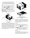
UNIT PRECAUTIONS
• Do not stand or walk on the unit.
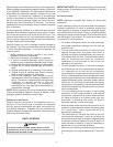
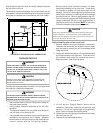
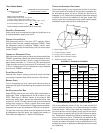
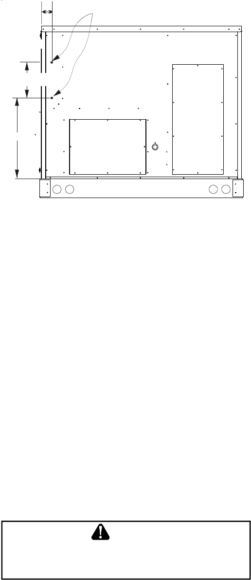
• Except for holes in the wiring entrances (see Figure
below), do not drill holes anywhere in panels or in
the base frame of the unit. Unit access panels
provide structural support.
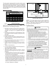
LOW VOLTAGE ENTRANCE
DIMPLES MARK DRILL LOCATIONS
HIGH VOLTAGE ENTRANCE
10 3/16”
3 3/4”
26 ½”
ELECTRICAL ENTRANCE LOCATIONS
• Do not remove any access panels until unit has been
installed on roof curb or field supplied structure.
• Do not roll unit across finished roof without prior
approval of owner or architect.
• Do not skid or slide on any surface as this may
damage unit base. The unit must be stored on a
flat, level surface. Protect the condenser coil
because it is easily damaged.
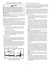
ROOF CURB INSTALLATIONS ONLY:
Curb installations must comply with local codes and should
be done in accordance with the established guidelines of the
National Roofing Contractors Association.
Proper unit installation requires that the roof curb be firmly
and permanently attached to the roof structure. Check for
adequate fastening method prior to setting the unit on the
curb.
Full perimeter roof curbs are available from the factory and
are shipped unassembled. Field assembly, squaring, level-
ing and mounting on the roof structure are the responsibility
of the installing contractor. All required hardware necessary
for the assembly of the sheet metal curb is included in the
curb accessory.
T
O
PREVENT
POSSIBLE
EQUIPMENT
DAMAGE
,
PROPERTY
DAMAGE
,
PERSONAL
INJURY
OR
DEATH
,
THE
FOLLOWING
BULLET
POINTS
MUST
BE
OBSERVED
WHEN
INSTA LLING
THE
UNIT
.
WARNING
• Sufficient structural support must be determined prior
to locating and mounting the curb and package unit.
• Ductwork must be constructed using industry
guidelines. The duct work must be placed into the
roof curb before mounting the package unit. Our full
perimeter curbs include duct connection frames to be
assembled with the curb. Cantilevered type curbs
are not available from the factory.