


18
5. Check supply fan rotation. If the supply fan is rotating
in the wrong direction, disconnect and lock off Single
Point Power Block. Do not attempt to change load
side wiring. Internal wiring is set at the factory to assure
that the supply fan and compressors all rotate in the
proper direction. Verification of correct supply fan
rotation at initial startup will also indicate correct
compressor rotation. Reconnect power and check for
proper operation.
6. Compressor contactor closes its contacts L1, L2 and
L3 to T1, T2 and T3 to provide power to the
compressor motor COMP 1; COMP 2, if conditions
are correct. In addition, contactor C1 closes its contact
L3 to T3 , energizing the condenser fan motor.
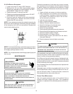
BURNHAZARD!
DONOTTOUCH!DISCHARGELINEMAYBEHO T!
WARNING
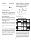
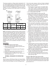
7. Check that each compressor is operating correctly.
The scroll compressors in these units MUST operate
in the proper rotation. To ensure the compressors are
operating in the correct direction, check the
compressor discharge line pressure or temperature
after each compressor is started.
The discharge pressure and discharge line
temperature should increase. If this does not occur
and the compressor is producing an exceptional
amount of noise, perform the following checks.
• Ensure all compressors and the supply fan motor
are operating in the proper direction. If a single
motor is operating backwards, check the power
wiring for that motor and correct any leads that
have been interchanged at the contactor or at the
motor.
• If all of the motors are operating backward,
disconnect the unit power supply and lock it in the
“OFF” position. Switch two leads of the power
supply at the unit Single Point Power Block.
Reconnect power and check for compressor and
supply fan motor operation.
8. With all safety devices closed, the system will continue
cooling operation until the thermostat is satisfied.
9. Disconnecting the jumper wire between R and Y1 and
Y2 and between R and G on TB1 terminal block will
simulate a satisfied thermostat. The compressors will
cycle off and IIC (pin 12) will initiate its time delay
cycle. The compressor and the supply fan will cycle
off.
10. After a time delay of approximately 3 minutes, the
compressor control circuits will be ready to respond
to a subsequent call for cooling from the wall
thermostat.
11. Open disconnect switch. Reconnect the field
thermostat wire at terminal R on terminal block TB1.
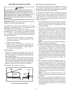
REFRIGERATION PERFORMANCE CHECK
Under normal summertime (full load) operating conditions,
superheat should be between 8°F and 12°F and sub-cooling
measured at the condenser outlet should be 15°F (nominal).
A 25°F to 35°F temperature difference should exist between
the entering condenser air and the temperature correspond-
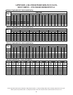
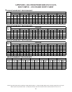
ing to the compressor saturated discharge pressure. Check
that compressor RLA corresponds to values shown in Ap-
pendix C. RLA draw can be much lower than values listed at
low load conditions and low ambient condensing tempera-
tures. Values in Appendix C can slightly exceed at high load
conditions and high ambient condensing temperatures.
GAS SUPPLY PRESSURES & REGULATOR ADJUSTMENTS
S
HOULD
OVERHEATING
OCCUR
OR
THE
GAS
SUPPLY
FAIL
TO
SHUT
OFF
,
TURN
OFF
THE
MANUAL
GAS
SHUTOFF
VALVE
EXTERNAL
TO
THE
UNIT
BEFORE
TURNING
OFF
THE
ELECT RICAL
SUPPLY
.
WARNING
T
O
AVOID
PROPERTY
DAMAGE
,
PERSONAL
INJURY
OR
DEATH
,
DO
NOT
FIRE
GAS
UNIT
WITH
FLUE
BOX
COVER
REMOVED
.
WARNING
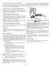
NOTE: Except during brief periods when gas pressures are
being measured by qualified service personnel, the furnace
access panel must always be secured in place when the
furnace is in operation. An inspection port in the access panel
is provided to monitor the flame.
The first step in checking out the gas-fired furnace is to test
the gas supply piping to the unit for tightness and purge the
system of air using methods outlined in the latest edition of
the National Fuel Gas Code ANSI Z223.1. Verify that the
disconnect switch is in the “OFF” position. A soapy water
solution should be used to check for gas leaks. Since the unit
is subject to considerable jarring during shipment, it is ex-
tremely important that all gas connections and joints be tested
for tightness. Gas piping downstream from the unit inlet should
be checked for leaks during the subsequent sequence check.
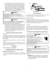
The supply gas pressure should be adjusted to 7.0" w.c. on
natural gas and 11.0" on LP gas with the gas burners operat-
ing. If there is more than one unit on a common gas line, the
pressures should be checked with all units under full fire. A
supply pressure tap is provided on the upstream side of the
gas valve. A manifold pressure tap is provided on the mani-
fold. The normal manifold pressure for full input is 3.5" w.c.
on natural gas and 10.0" w.c. for propane gas. Minimum gas
supply pressure is 5.5" w.c. for natural gas and 11.0" for pro-
pane gas. In order to obtain rating, gas supply pressure must
be 11.0" w.c. for propane gas.