


7
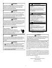
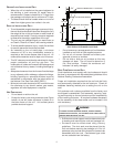
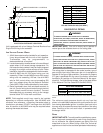
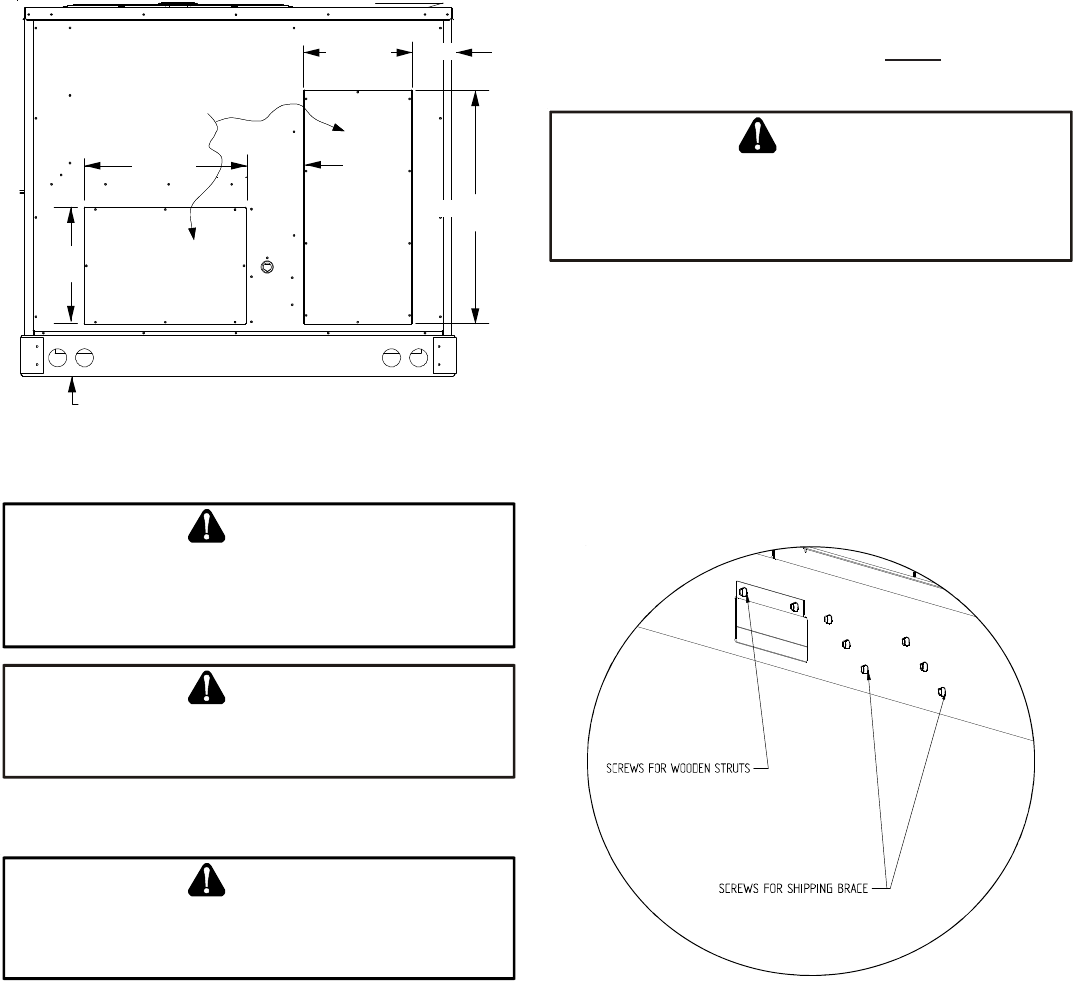
Ensure that the top of the duct connection frame is flush with
the top of the roof curb.
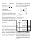
Flexible duct connectors between the unit and ducts are rec-
ommended. Insulate and weatherproof all external ductwork
and joints as required and in accordance with local codes.
RETURN
SUPPLY
13 7/8”
28 3/8”
7 3/8”
12 5/8”
5 7/8”
6 1/4”
36 3/8”
REMOVE
COVERS
HORIZONTAL DISCHARGE DUCT CONNECTIONS
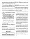
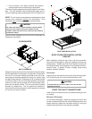
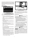
RIGGING DETAILS
T
O
PREVENT
PROPERTY
DAMAGE
,
THE
UNIT
SHOULD
REMAIN
IN
AN
UPRIGHT
POSITION
DURING
ALL
RIGGING
AND
MOVING
OPERATIONS
.
T
O
FACILITATE
LIFTING
AND
MOVING
WHEN
A
CRANE
IS
USED
,
PLACE
THE
UNIT
IN
AN
ADEQUATE
CABLE
SLING
.
WARNING
D
O
NOT
LIFT
UNITS
TWO
AT
A
TIME
.P
ROVISIONS
FOR
FORKS
HAVE
BEEN
INCLUDED
IN
THE
UNIT
BASE
FRAME
.M
INIMUM
FORK
LENGTH
IS
48”
TO
PREVENT
DAMAGE
TO
THE
UNIT
.
CAUTION
Provisions for forks have been included in the unit base frame.
No other fork locations are approved.
T
O
PREVENT
POSSIBLE
EQUIPMENT
DAMAGE
,
PROPERTY
DAMAGE
,
PERSONAL
INJURY
OR
DEATH
,
THE
FOLLOWING
BULLET
POINTS
MUST
BE
OBSERVED
WHEN
INSTA LLING
THE
UNIT
.
WARNING
• Unit must be lifted by the four lifting holes located at
the base frame corners.
• Lifting cables should be attached to the unit with
shackles.
• The distance between the crane hook and the top of
the unit must not be less than 60”.
• Two spreader bars must span over the unit to prevent
damage to the cabinet by the lift cables. Spreader
bars must be of sufficient length so that cables do not
come in contact with the unit during transport.
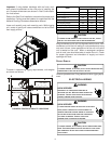
Remove wood struts mounted beneath unit base
frame before setting unit on roof curb. These struts
are intended to protect unit base frame from fork lift
damage. Removal is accomplished by extracting the
sheet metal retainers and pulling the struts through
the base of the unit. Refer to rigging label on the unit.
• Your unit may be equipped with a steel shipping brace
located underneath the unit (under compressors). If
installing on a roof curb, the brace MUST be removed.
Follow the following instructions for removal.
W
HEN
UNIT
IS
SUSPENDED
,
BOARDS
AND
SHIPPING
BRACE
WILL
DROP
WHEN
SCREWS
ARE
REMOVED
.T
O
PREVENT
PERSONAL
INJURY
,STANDCLEAR.
R
EMOVE
FORK
HOLE
BRACKETS
,
BOARDS
AND
SHIPPING
BRACE
FROM
BOTTOM
OF
UNIT
BEFORE
PLACING
UNIT
ONTO
CURB
.
CAUTION
Before installing this unit on a roof curb:
1. Remove wooden struts per installation instructions.
These are the struts that are located in the fork holes
and are used to protect the unit from damage while
lifting with forks.
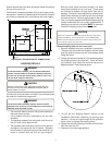
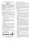
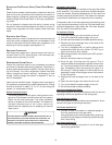
2. Locate and remove the twelve (12) screws that attach
the shipping brace to the side rails. There will be six
(6) screws on each side of the unit and they are in a
diagonal pattern. See following figure.
3. Lift unit per the “Rigging Details” section of the
installation instructions, observing all warnings and
cautions. Lift the unit high enough off the ground to
reach under and grasp the shipping brace.
4. Rotate the brace by tapping the ends until the brace
falls free from the unit.
5. Dispose of the brace appropriately.