


9
LOW VOLTAGE
BLOCK
MAIN POWER
LOW VOLTAGE
ENTRANCE
POWER THRU
THE CURB
CONTROL BOX
F
AILURE
OF
UNIT
DUE
TO
OPERATION
ON
IMPROPER
LINE
VOLTAGE
OR
WITH
EXCESSIVE
PHASE
UNBALANCE
CONSTITUTES
PRODUCT
ABUSE
AND
WILL
VOID
YOUR
WARRANTY
AND
MAY
CAUSE
SEVERE
DAMAGE
TO
THE
UNIT
ELECTRICAL
COMPONENTS
.
WARNING
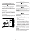
Areas Without Convenience Outlet
It is recommended that an independent 115V power source
be brought to the vicinity of the roof top unit for portable lights
and tools used by the service mechanic.
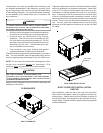
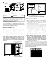
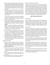
UNITS INSTALLED ON ROOF TOPS
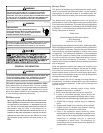
Main power and low voltage wiring may enter the unit through
the condenser end or through the roof curb. Install conduit
connectors at the desired entrance locations. External con-
nectors must be weatherproof. All holes in the unit base must
be sealed (including those around conduit nuts) to prevent
water leakage into building. All required conduit and fittings
are to be field supplied.
Supply voltage to roof top unit must not vary by more than
10% of the value indicated on the unit’s data plate. Phase
voltage unbalance must not exceed 2%. Contact your local
power company for correction of improper voltage or phase
unbalance.
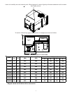
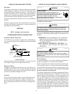
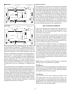
HIGH VOLTAGE ENTRANCE
LOW VOLTAGE ENTRANCE
1:4
30 1/4”*
12 3/8”
(REMOVE PLUG)
* (6 Ton - 34 1/4”)
4 1/2”
47 1/2”
7 1/2”
POWER THRU
THE CURB
3.5 DIA.
RETURN
SUPPLY
ELECTRICAL ENTRANCE AND THRU CURB
LOW VOLTAGE CONTROL WIRING
1. A 24V thermostat must be installed for unit operation.
It may be purchased with the unit or field -supplied.
Thermostats may be programmable or
electromechanical as required.
2. Locate thermostat or remote sensor in the conditioned
space where it will sense average temperature. Do
not locate the device where it may be directly exposed
to supply air, sunlight or other sources of heat. Follow
installation instructions packaged with the thermostat.
3. Use #18 AWG wire for 24V control wiring runs not
exceeding 75 feet. Use #16 AWG wire for 24V control
wiring runs not exceeding 125 feet. Use #14 AWG
wire for 24V control wiring runs not exceeding 200
feet. Low voltage wiring may be National Electrical
Code (NEC) Class 2 where permitted by local codes.
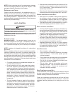
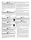
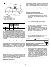
4. Route thermostat wires from sub-base terminals to
the unit. Control wiring should enter through the
condenser panel opening indicated in “Electrical
Entrance Locations” figure. Connect thermostat and
any accessory wiring to low voltage terminal block
TB1 in the main control box.
NOTE: Field-supplied conduit may need to be installed
depending on unit/curb configuration. Use #18 AWG solid
conductor wire whenever connecting thermostat wires to
terminals on sub-base. DO NOT use larger than #18 AWG
wire. A transition to #18 AWG wire may be required before
entering thermostat sub-base.
TERMINAL THERMOSTAT
Red R (24V)
Green G (Fan)
Orange O (Rev. Valve)
White W1 (Heat, 2nd)*
Brown W2 (Heat 3rd)*
Yellow Y (Cool)
C
(
Blue
)
C
(
Common
)
*Optional field installed heat connections
CPC/H 036 THROUGH 072