


11
TOOLS REQUIRED
Refrigeration gauge and manifold
Voltmeter
Clamp-on ammeter
Ohmmeter
Test lead
(Minimum #16 AWG with insulated alligator clips)
Air temperature measuring device
General refrigeration mechanics’ tools
TEMPORARY HEATING OR COOLING
If the unit is to be used for temporary heating or cooling, a
“Startup, Adjustments, and Checks” must first be performed
in accordance with this manual. Failure to comply with this
requirement will void the warranty. After the machines are
used for temporary heating or cooling, inspect the coils, fans,
and motors for unacceptable levels of construction dust and
dirt and install new filters.
CONTRACTOR RESPONSIBILITY
The installing contractor must be certain that:
• All supply and return air ductwork is in place and
corresponds with installation instructions.
• All thermostats are mounted and wired in accordance
with installation instructions.
• All electric power, all gas, hot water or steam line
connections, and the condensate drain installation
have been made to each unit on the job. These main
supply lines must be functional and capable of
operating all units simultaneously.
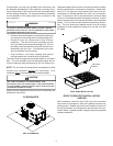
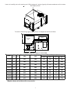
ROOF CURB INSTALLATION CHECK
Inspect the roof curb for correct installation. The unit and curb
assembly should be level. Inspect the flashing of the roof
mounting curb to the roof, especially at the corners, for good
workmanship. Also check for leaks around gaskets. Note any
deficiencies in a separate report and forward to the contrac-
tor.
OBSTRUCTIONS, FAN CLEARANCE AND WIRING
Remove any extraneous construction and shipping materi-
als that may be found during this procedure. Rotate all fans
manually to check for proper clearances and that they rotate
freely. Check for bolts and screws that may have jarred loose
during shipment to the jobsite. Retighten if necessary. Re-
tighten all electrical connections.
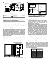
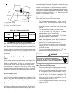
PRE-STARTUP PRECAUTIONS
It is important to your safety that the unit has been properly
grounded during installation. Check ground lug connection
in main control box for tightness prior to closing circuit breaker
or disconnect switch. Verify that supply voltage on line side
of disconnect agrees with voltage on unit identification plate
and is within the utilization voltage range as indicated in Ap-
pendix C Electrical Data.
System Voltage - That nominal voltage value assigned to a
circuit or system for the purpose of designating its voltage
class.
Nameplate Voltage - That voltage assigned to a piece of
equipment for the purpose of designating its voltage class
and for the purpose of defining the minimum and maximum
voltage at which the equipment will operate.
Utilization Voltage - The voltage of the line terminals of the
equipment at which the equipment must give fully satisfac-
tory performance. Once it is established that supply voltage
will be maintained within the utilization range under all sys-
tem conditions, check and calculate if an unbalanced condi-
tion exists between phases. Calculate percent voltage un-
balance as follows:
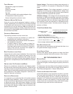
Three Phase Models Only
3) PERCENT VOLTAGE
UNBALANCE
2) MAXIMUM VOLTAGE DEVIATIONS
FROM AVERAGE VOLTAGE
1) AVERAGE VOLTAGE
HOW TO USE THE FORMULA:
EXAMPLE: With voltage of 220, 216, and 213
1) Average Voltage = 220+216+213=649 / 3 = 216
2) Maximum Voltage Deviations from Average Voltage = 220 - 216 = 4
3) Percent Voltage Unbalance = 100 x = = 1.8%
Percent voltage unbalance MUST NOT exceed 2%
.
4
216
400
216
= 100 X
FIELD DUCT CONNECTIONS
Verify that all duct connections are tight and that there is no
air bypass between supply and return.
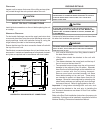
FILTER SECTION CHECK
Remove filter section access panels and check that filters
are properly installed. Note airflow arrows on filter frames.
BELT DRIVE MODELS ONLY
BEARING CHECK
Prior to energizing any fans, check and make sure that all
setscrews are tight so that bearings are properly secured to
shafts.
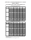
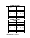
For heat pump units, the airflow must be adjusted so that the
air temperature rise falls within the ranges given stated on
Data Plate (see Appendix A - Blower Performance).
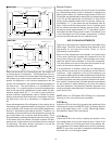
TENSION AND ALIGNMENT ADJUSTMENT
Correct belt tension is very important to the life of your belt.
Too loose a belt will shorten its life; too tight, premature mo-
tor and bearing failure will occur. Check you belt drive for
adequate “run-in” belt tension by measuring the force required
to deflect the belt at the midpoint of the span length. Belt
tension force can be measured using a belt tension gauge,
available through most belt drive manufacturers.